
This article was updated in July 12, 2026 with new products and information by Mark S. Taylor
Trapped air in a cooling system doesn’t cause a slow, gradual overheating problem. It causes rapid overheating — sometimes within 10 minutes of starting a freshly flushed or repaired engine — because an air pocket covering the thermostat makes the thermostat read air temperature instead of coolant temperature, the water pump spins against vapor instead of coolant, and the actual coolant in the system can’t circulate fast enough to carry heat away. The engine temperature gauge climbs. The heater blows cold. And most drivers don’t connect either symptom to trapped air until the gauge is in the red.
The procedure for removing that air depends entirely on what type of cooling system you have. Most articles treat all vehicles the same. They’re not. Here’s the complete picture for every system type, including the professional vacuum fill method that eliminates the bleed procedure entirely.
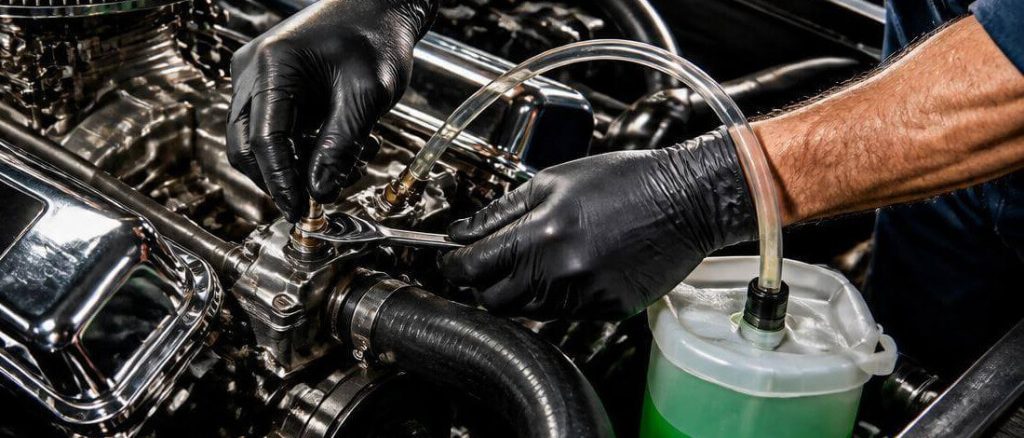
Contents
- 1 Why Bleeding a Cooling System Matters — What Trapped Air Actually Does
- 2 Identify Your System Type First — Two Completely Different Procedures
- 3 Tools and Materials Needed
- 4 Method 1 — The Traditional Manual Bleed (Unpressurized Overflow System)
- 4.1 Step 1 — Elevate the Vehicle’s Nose (Strongly Recommended)
- 4.2 Step 2 — Confirm the Engine Is Cold and Open the Radiator Cap
- 4.3 Step 3 — Fill the Radiator to the Base of the Filler Neck
- 4.4 Step 4 — Set the Cabin Controls to Maximum Heat Before Starting the Engine
- 4.5 Step 5 — Start the Engine and Monitor Without Closing the Cap
- 4.6 Step 6 — Squeeze and Burp the Upper Radiator Hose
- 4.7 Step 7 — Wait for the Thermostat to Open
- 4.8 Step 8 — Confirm Completion and Install the Cap
- 4.9 The Squeeze-and-Burp Technique — How and Why It Works
- 5 Method 2 — Bleeding a Pressurized Degas Bottle System
- 5.1 Step 1 — Cold Engine, Identify the Degas Bottle
- 5.2 Step 2 — Fill Through the Degas Bottle Cap
- 5.3 Step 3 — Set Cabin Controls to Maximum Heat
- 5.4 Step 4 — Start the Engine With the Degas Bottle Cap Removed
- 5.5 Step 5 — Top Off the Degas Bottle as Coolant Level Drops
- 5.6 Step 6 — Confirm Bubble Cessation and Install Cap
- 6 Method 3 — The Vacuum Fill Method (Professional Technique, DIY Accessible)
- 6.1 Step 1 — Ensure the Engine Is Cold and All Connections Are Tight
- 6.2 Step 2 — Attach the Vacuum Tool to the Fill Point
- 6.3 Step 3 — Evacuate the System to 25 to 28 Inches of Mercury
- 6.4 Step 4 — Perform the Vacuum Hold Test
- 6.5 Step 5 — Draw Coolant Into the System
- 6.6 Step 6 — Top Off and Verify Level
- 6.7 Step 7 — Start the Engine and Verify
- 7 Vehicles That Require the Vacuum Fill Method
- 8 Vehicle-Specific Bleed Screw Locations and Procedures
- 9 How To Confirm the Bleed Is Complete
- 10 When Bleeding Doesn’t Fix It — The Combustion Gas Diagnostic
- 11 Cooling System Bleed Cost — DIY vs. Shop
- 12 How To Prevent Air From Getting Trapped in the Future
- 13 FAQs About How To Bleed a Cooling System
- 14 The Expert Verdict
Why Bleeding a Cooling System Matters — What Trapped Air Actually Does
The cooling system moves heat from the engine to the radiator through forced coolant circulation — the water pump pushing coolant continuously through the block, head, heater core, and radiator. Every component in that loop needs to be filled with liquid coolant for the system to work. Air does not transfer heat effectively. An air pocket in the wrong location stops heat transfer at that location entirely.
Three specific air lock locations cause three specific failure modes.
Air lock at the thermostat housing: The thermostat is a temperature-sensing valve. It opens when coolant temperature reaches its rated threshold — typically 190°F to 210°F — and closes when temperature drops below that threshold. The sensor that triggers the thermostat is the wax pellet element inside the thermostat itself. If an air pocket covers this element, the thermostat is reading air temperature — not coolant temperature. The air in the housing is heated by proximity to the engine block to 200°F to 250°F. The thermostat opens. But there’s no liquid coolant flowing through the main circuit — the air pocket is blocking circulation. The engine overheats while the thermostat is technically open, because there’s no liquid coolant moving through the system to carry heat to the radiator. The coolant temperature sensor — also often located near the thermostat housing — reads the same air pocket and reports erratic or elevated temperatures to the PCM.
Air lock at the water pump inlet: The water pump is designed to push liquid. If the pump inlet is exposed to air, the pump impeller spins against vapor and generates no meaningful flow — a condition called vapor lock. No coolant circulates. No heat transfers. The engine overheats within minutes of startup. This air lock is most common after a completely dry fill — post-head-gasket replacement, post-water-pump replacement — where no coolant is present in the system at all before filling begins.
Air lock in the heater core: The heater circuit is a small-diameter parallel loop that branches off the main cooling circuit. Air trapped in this loop doesn’t cause overheating — the main circuit can still circulate normally. What it causes is a heater that blows cold air at full operating temperature. The heater core is filled with air instead of hot coolant, so no heat transfers to the cabin. This specific air lock often doesn’t resolve with basic system bleeding because the heater circuit’s small diameter and parallel routing means the main circuit’s flow doesn’t automatically push air out of the heater loop.
Identify Your System Type First — Two Completely Different Procedures
Before touching a wrench or opening a cap, identify which type of cooling system your vehicle has. The bleed procedure for each type is different enough that following the wrong procedure leaves the system incompletely bled.
System Type 1 — Traditional Unpressurized Overflow Tank
The radiator has a pressure cap — a cap with a spring-loaded pressure relief valve rated at 13 to 16 PSI. The overflow tank is a separate reservoir connected to the radiator by a small hose from the overflow nipple on the radiator cap. The overflow tank cap is a simple screw-on plastic cover with no pressure rating — it’s atmospheric. Coolant fills into the radiator through the pressure cap opening. The overflow tank catches coolant during thermal expansion and returns it when the system cools.
Identification: The pressure-rated cap (with a PSI rating stamped on it) is on the radiator filler neck. The reservoir cap is plain plastic with no pressure rating.
Bleed procedure for this system: Method 1 (Traditional Manual Bleed) described below.
System Type 2 — Pressurized Degas Bottle
The degas bottle is sealed and pressurized — it IS the pressure vessel for the system. The cap on the degas bottle has the pressure rating. There is no pressure cap on the radiator — the radiator either has no filler neck at all, or has a secondary low-pressure or non-sealing cap that is NOT the fill point. Coolant fills into the degas bottle. The degas bottle connects to the top of the radiator through an internal standpipe or a separate hose, maintaining the system’s highest coolant level and acting as the air separator.
Identification: The pressure-rated cap (PSI stamped on it) is on the reservoir/bottle, not on the radiator. Common on virtually all modern Ford vehicles (F-150, Focus, Fusion, Edge, Explorer), BMW, Mercedes, Audi, VW, and Volvo.
Bleed procedure for this system: Method 2 (Degas Bottle Bleed) described below.
The simplest identification check: squeeze the reservoir cap. If it feels like a radiator cap — spring resistance when you push down on it before twisting — it’s a pressurized degas bottle. If it opens freely with no spring resistance, it’s an overflow tank and the radiator cap is your fill point.

Tools and Materials Needed
Have everything on hand before starting. A mid-procedure search for distilled water or a funnel costs time the temperature gauge doesn’t have.
For all methods:
- Correct OEM-specification coolant (at least 1 quart; 1 gallon preferred for safety margin)
- Distilled water for mixing if using concentrate
- Clean funnel
- Rags for spill containment — coolant on a hot engine produces vapor and is slippery on concrete
- Flashlight for reservoir level inspection
For the traditional manual bleed (Method 1):
- Vehicle ramps or wheel chocks (optional but recommended for nose elevation)
- Bleed screw wrench (6mm, 8mm, or 10mm depending on application — check the service manual)
For the degas bottle bleed (Method 2):
- No additional tools beyond the basics — the procedure is observation-based
For the vacuum fill method (Method 3):
- Venturi vacuum fill tool (UView Airlift, Lisle 24680, OTC 4563, or equivalent: $35–$85)
- Shop air supply (90 PSI minimum)
- Coolant supply container
For diagnosing recurring air:
- Combustion gas block test kit ($25–$40 at any auto parts store)
Method 1 — The Traditional Manual Bleed (Unpressurized Overflow System)
Do this with a cold engine only. A hot, pressurized cooling system can spray scalding coolant when the cap is opened. Wait at least 2 hours after the engine was last run, or confirm by touch that the upper radiator hose is cool before opening anything.
Step 1 — Elevate the Vehicle’s Nose (Strongly Recommended)
Drive the front wheels onto vehicle ramps or park with the front of the vehicle on a curb or incline that raises the nose 3 to 4 inches above the rear. This positions the thermostat housing — which is at the front of the engine on most transverse-mounted FWD vehicles — above the heater core and radiator. Air rises. With the nose elevated, air migrates toward the open radiator cap rather than collecting in the thermostat housing or heater circuit. This single step reduces bleeding time by 30 to 50 percent and is the technique most DIY guides skip entirely.
Step 2 — Confirm the Engine Is Cold and Open the Radiator Cap
Squeeze the upper radiator hose before opening the cap — a hose with no resistance (collapses easily under hand pressure) confirms the system is not pressurized. Open the radiator cap by pressing down and turning to the first stop, releasing any residual pressure, then continuing to the full open position. Set the cap aside where it won’t be contaminated with dirt.
Step 3 — Fill the Radiator to the Base of the Filler Neck
Pour the correct OEM-specification coolant through the funnel into the radiator filler neck. Fill slowly to allow air to escape upward as the coolant descends into the system. Fill until coolant reaches the bottom of the filler neck threads — not the top, which would overflow during thermal expansion. Also top off the overflow reservoir to the COLD MAX line.
Step 4 — Set the Cabin Controls to Maximum Heat Before Starting the Engine
Turn the temperature control to the highest setting (full hot) and the blower fan to maximum speed. This is mandatory, not optional. On vehicles with a heater control valve — a valve in the heater hose that regulates coolant flow to the heater core — the valve position is controlled by the cabin temperature setting. A cold temperature setting closes the valve, sealing the heater circuit. Air trapped in the heater circuit has no path to escape. Maximum heat setting ensures the heater control valve is fully open and coolant can circulate through the heater core during the bleed procedure.
Step 5 — Start the Engine and Monitor Without Closing the Cap
Start the engine and allow it to idle. Do not install the radiator cap yet. Watch the coolant in the filler neck — you’ll see movement and possibly small bubbles as the water pump begins circulating coolant. Keep the coolant level topped up as it drops — this drop is normal as coolant fills previously air-occupied passages. Add coolant in small amounts to keep the filler neck full without overflowing.
Step 6 — Squeeze and Burp the Upper Radiator Hose
With the engine running and idling, grip the upper radiator hose firmly with both hands and squeeze it repeatedly — compress the hose fully and release, approximately once per second, for 10 to 15 repetitions. Watch the coolant surface in the radiator filler neck. Air bubbles rising and breaking at the surface confirm air is being pushed from the system. Continue squeezing until no bubbles appear on the releases. If the coolant level drops during this process, top it off before continuing.
Repeat the squeeze on the lower radiator hose — this helps prime the water pump and dislodge air from the pump inlet area. Squeeze the heater hoses (the smaller hoses running to the firewall) to push air through the heater circuit specifically.
Step 7 — Wait for the Thermostat to Open
Continue monitoring the coolant level and temperature gauge. At approximately 190°F to 210°F, the thermostat opens — marked by a sudden surge of hot coolant through the upper radiator hose. You’ll feel this if you’re holding the hose lightly — a pulse of increased flow and heat. The coolant level in the filler neck may drop suddenly as the thermostat opens and coolant rushes into the radiator. Add coolant immediately to maintain the level at the filler neck base.
After the thermostat opens, squeeze the upper hose 10 more times. The most significant air purge often occurs immediately after the thermostat opens, as the pressure differential between the engine side and the radiator side pushes the final air pocket through.
Step 8 — Confirm Completion and Install the Cap
The bleed is complete when: the temperature gauge is stable in the normal operating range (between one-quarter and three-quarters of the gauge arc), the upper radiator hose is hot to the touch (confirming coolant flow through the radiator), the heater produces genuinely hot air from the vents (above 120°F — you cannot hold your hand in the airstream for more than a second), and no bubbles appear when squeezing the hoses. Install the radiator cap, tighten to the locked position, and lower the vehicle off the ramps if elevated. Check the coolant level again after the engine cools completely — top off to the COLD MAX line on the reservoir if needed.
The Squeeze-and-Burp Technique — How and Why It Works
The squeeze-and-burp works by creating a pressure pulse in the coolant. When you compress the hose, you increase local pressure momentarily in that section of the circuit. When you release, the hose springs back to its normal diameter, creating a momentary low-pressure zone that draws coolant forward from the reservoir while pushing the contents of the compressed section away from the squeeze point — toward the open radiator neck.
Air bubbles, being less dense than coolant, rise toward the highest open point in the system — the open radiator cap. Each squeeze-and-release cycle moves a small volume of air upward through the coolant column. The burp you see at the surface is that air escaping.
The technique is most effective on the upper radiator hose because this hose connects the engine’s highest coolant exit point (the thermostat housing) to the radiator inlet — the most direct path for air to exit the system. Squeezing the lower hose primes the water pump by drawing coolant into the pump inlet, reducing the likelihood of vapor lock on initial circulation. Squeezing the heater hoses addresses the parallel heater circuit where air often remains trapped even after the main circuit is fully bled.

Method 2 — Bleeding a Pressurized Degas Bottle System
This procedure applies to Ford vehicles (virtually all 2005+ models), BMW, Audi, VW, Mercedes-Benz, Volvo, and most modern European applications. If you follow the traditional Method 1 procedure on one of these vehicles, you will either fill the wrong reservoir or never achieve proper bleed confirmation — because the visual indicators are completely different.
The critical difference: on a degas bottle system, the bottle itself is the highest point in the system and the air separator. Air rises from the radiator and engine through the standpipe inside the degas bottle and exits at the coolant surface inside the bottle. The bleed procedure involves watching the bottle’s coolant surface for bubbles while the engine runs — not watching a radiator filler neck.
Step 1 — Cold Engine, Identify the Degas Bottle
Confirm the pressure-rated cap is on the degas bottle, not on the radiator. On a Ford F-150 or Focus, the degas bottle is typically mounted on the passenger side of the engine bay near the firewall or inner fender, connected to the radiator by a hose at the bottom and to the top of the radiator or engine by the internal standpipe connection. The radiator has no fill cap on most Ford applications — only a lower drain petcock.
Step 2 — Fill Through the Degas Bottle Cap
With the engine cold, remove the degas bottle cap by pressing down and turning (same mechanism as a radiator cap). Fill with the correct coolant until the level reaches the MAX COLD line on the bottle. Do not overfill — the degas bottle needs airspace above the coolant for the air separation function.
Step 3 — Set Cabin Controls to Maximum Heat
Same reasoning as Method 1 — ensure the heater control valve is fully open to allow the heater circuit to bleed simultaneously with the main circuit.
Step 4 — Start the Engine With the Degas Bottle Cap Removed
Start the engine and allow it to idle with the degas bottle cap removed. Watch the coolant surface inside the bottle — specifically watch for bubbles rising up through the coolant and breaking at the surface. These bubbles are air being expelled from the radiator and engine passages through the standpipe. As documented in Ford’s OEM service procedures, the correct bleed confirmation for degas bottle systems is observation of bubbles transitioning to no bubbles at the bottle surface — not the hose squeeze technique used on traditional systems.
Step 5 — Top Off the Degas Bottle as Coolant Level Drops
As air leaves the system, coolant fills the vacated passages and the level in the degas bottle drops. Top off with coolant to maintain the level above the MIN line. Do not allow the bottle to run dry — this reintroduces air into the standpipe.
Step 6 — Confirm Bubble Cessation and Install Cap
The bleed is complete when: no bubbles appear at the coolant surface in the degas bottle for at least 30 seconds of idling, the temperature gauge is stable in the normal operating range, and the heater produces hot air from the vents. Install the degas bottle cap, tighten to the locked position. Check the level after the engine cools — top off to the COLD MAX line if needed. On many degas bottle vehicles, a small level drop after the first cold-to-hot-to-cold cycle is normal as final air works its way out.
Method 3 — The Vacuum Fill Method (Professional Technique, DIY Accessible)
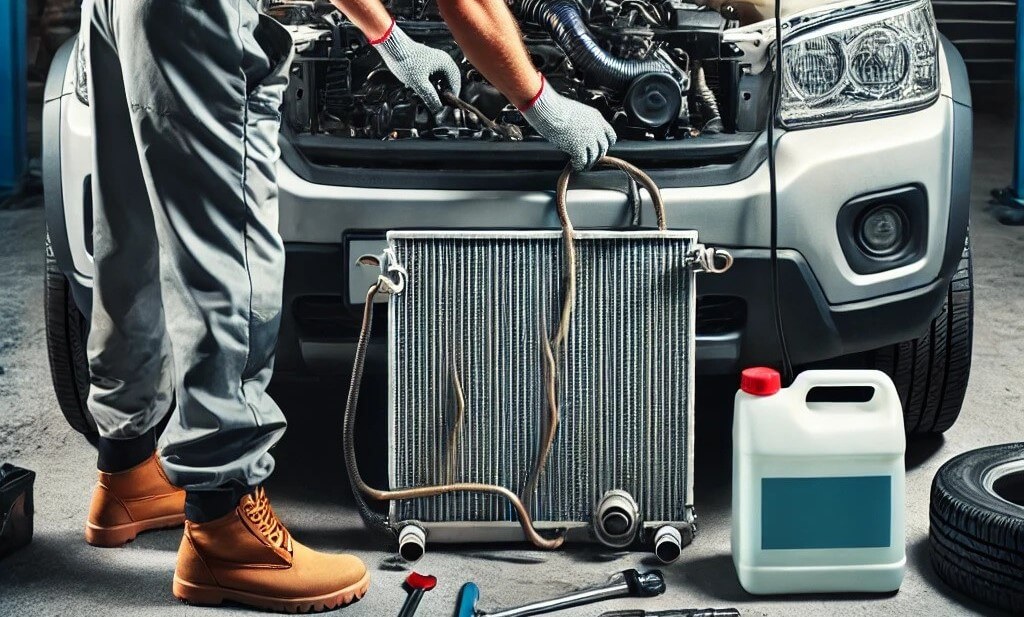
This is how professional shops bleed cooling systems when they have the right equipment — and you can do it at home for $35 to $85 in tooling. Instead of filling the system and then pushing air out, the vacuum method pulls air out first, then draws coolant in under vacuum. The result is a completely air-free system before the engine is ever started — no squeeze-and-burp, no nose elevation procedure, no monitoring the temperature gauge during a 45-minute warm-up cycle.
The tool is a venturi-type vacuum generator — a device that attaches to the cooling system’s fill point and uses shop air (90 PSI minimum) flowing through an internal venturi to create a vacuum. Common brands available at AutoZone and O’Reilly include UView Airlift, Lisle 24680, and OTC 4563. The tool includes adapters to fit standard radiator cap openings and most degas bottle openings.
Step 1 — Ensure the Engine Is Cold and All Connections Are Tight
Before applying vacuum to the system, confirm every hose clamp is tight, every component that was replaced is fully torqued, and the drain petcock is closed. Vacuum testing will reveal leaks — but it’s better to catch obvious ones visually before putting the system under vacuum.
Step 2 — Attach the Vacuum Tool to the Fill Point
Select the correct adapter from the tool kit for your radiator cap or degas bottle opening. Thread the adapter onto the fill point and connect the vacuum tool body to the adapter. Connect the shop air supply to the tool’s air inlet. The venturi inside the tool creates vacuum when shop air flows through it — no separate vacuum pump required.
Step 3 — Evacuate the System to 25 to 28 Inches of Mercury
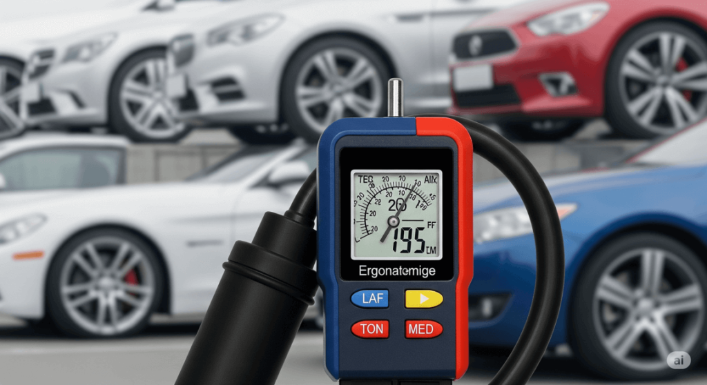
Open the vacuum valve on the tool and allow shop air to flow. Watch the vacuum gauge on the tool — the system pressure drops as air is pulled from the cooling passages. Allow the vacuum to build until the gauge reads 25 to 28 inches of mercury. Per UView tool specifications, this vacuum level ensures all passages including the heater core and block water jackets are evacuated of air. At 25 inches of mercury, the atmospheric pressure difference is sufficient to draw coolant into even the smallest passages — including the heater core’s 3 to 5mm internal tubes — without manual intervention.
Step 4 — Perform the Vacuum Hold Test
Close the vacuum valve and disconnect the shop air while watching the vacuum gauge. Hold for 60 seconds. A gauge reading that remains stable (drops less than 2 inches of mercury in 60 seconds) confirms the system is sealed — no leaks. A gauge reading that drops significantly indicates a leak path: a loose hose clamp, an incompletely seated gasket, or an open drain. Find and fix the leak before filling. This vacuum hold test is the most efficient leak test available for a cooling system — it simultaneously reveals any leak path that would admit air after filling.
Step 5 — Draw Coolant Into the System
Submerge the fill hose from the vacuum tool into your coolant supply (a bucket of pre-mixed 50/50 coolant or a gallon jug). Open the fill valve on the tool. The vacuum in the system draws coolant through the fill hose and into the cooling passages — all passages simultaneously, including the heater core. Watch the coolant level in the supply container drop as the system fills. The fill completes when the vacuum gauge drops to zero and the flow stops — the system is full and equalized to atmospheric pressure.
Step 6 — Top Off and Verify Level
Remove the vacuum tool. Check the coolant level at the fill point — it should be at or slightly below the full level since the system is under vacuum when the tool is removed and a small amount of air may enter as the tool disconnects. Top off to the correct COLD level mark. Install the radiator cap or degas bottle cap.
Step 7 — Start the Engine and Verify
Start the engine and allow it to reach operating temperature. The system is already air-free, so no squeeze-and-burp is needed. Confirm the temperature gauge stabilizes in the normal range, the heater produces hot air, and the upper radiator hose becomes hot to the touch when the thermostat opens. Check the coolant level after the engine returns to cold — a small drop of 0.25 to 0.5 inches in the reservoir is normal as the last traces of air work out. Top off as needed.
Vehicles That Require the Vacuum Fill Method
Post-Head-Gasket Replacement:
After a head gasket replacement, the cooling system is completely dry. Every passage — block water jackets, head passages, heater core, all hoses — contains only air. Filling this system from the top and pushing air out is a 60 to 90 minute procedure with real risk of incomplete bleeding, particularly in the heater circuit and the water pump inlet zone. The vacuum fill method evacuates the entire system in 5 minutes and fills it completely in 3 to 5 minutes. For any post-head-gasket fill, use the vacuum method.
V-Configuration Engines (V6, V8, V10):
V-engines have two cylinder heads, two banks of passages, and significantly more complex coolant routing than inline engines. The cross-bank passages, the intake manifold coolant crossover, and the dual thermostat configurations on some applications create multiple potential air trap locations that the traditional squeeze-and-burp method may not reach. The vacuum fill method fills all passages simultaneously regardless of routing complexity.
Vehicles With Known Difficult Bleed Histories:
Some vehicle platforms — BMW N54/N55 engines, GM 3.6L LFX, Ford 6.2L V8 — are documented as requiring extended or multi-cycle bleeds due to complex coolant routing. A quick internet search for your specific engine plus “cooling system bleed difficulty” before starting the job tells you whether you’re dealing with a straightforward 30-minute procedure or a 90-minute multi-cycle that’s much better handled by vacuum fill.
Vehicle-Specific Bleed Screw Locations and Procedures
Some vehicles — particularly European imports — have dedicated bleed screws at specific high points in the cooling system. These screws supplement the main fill procedure and must be opened before and during the fill to allow air to escape from locations that the fill point procedure can’t reach.
Common bleed screw locations by vehicle family:
- BMW (E46, E90, E39, F30 series): small bleed screw on the upper radiator hose fitting or on the coolant pipe near the thermostat; 6mm hex fitting; open 1 to 2 turns during fill, close when coolant flows without bubbles
- Mercedes-Benz (C-Class, E-Class): bleed screw on the expansion tank or upper coolant crossover pipe; varies by model year; 8mm hex on older applications, quarter-turn valve on newer
- VW/Audi (2.0T, 3.0T): bleeder nipple on the upper coolant crossover pipe between the heads; squeeze the rubber nipple to release trapped air rather than using a wrench fitting
- Domestic applications with bleed screws: some GM 3.6L engines have a bleed screw on the thermostat housing; some Ford EcoBoost applications have a bleed fitting on the coolant crossover
The seized bleed screw complication:
A bleed screw that won’t turn with light finger pressure should not be forced. Bleed screws on European vehicles are typically soft brass or aluminum and will shear at surprisingly low torque. Apply penetrating oil (PB Blaster or equivalent), allow 20 to 30 minutes of dwell time, and retry with light hand pressure only. A sheared bleed screw in an aluminum housing requires screw extraction and thread repair — a $150 to $300 shop procedure that adds significant time and cost to a routine bleed. If the screw has been seized for years, the vacuum fill method is the better alternative — it achieves complete air removal without requiring the bleed screw to open.
How To Confirm the Bleed Is Complete
The bleed procedure is finished when all four of these indicators are simultaneously true. Any one failing indicates the procedure is incomplete.
Indicator 1 — Temperature Gauge Stable in Normal Range
The temperature gauge is stable between one-quarter and three-quarters of the gauge arc — in the normal operating zone — with the engine at full operating temperature and the heater running at maximum. The gauge does not climb beyond this range or spike. A temperature gauge that climbs beyond the normal range during or after the bleed procedure indicates a significant remaining air pocket covering the coolant temperature sensor or blocking flow through a critical passage.
Indicator 2 — Upper Radiator Hose Hot to the Touch
With the engine at operating temperature (after thermostat opening), grip the upper radiator hose. It should be too hot to hold — above 190°F. A cold upper radiator hose at operating temperature indicates the thermostat hasn’t opened (the engine hasn’t reached operating temperature yet) or the thermostat is stuck closed. A warm-but-not-hot upper hose indicates partial flow — the thermostat may be partially open or an air pocket is restricting flow through the hose.
Indicator 3 — Heater Produces Genuinely Hot Air
Set the cabin temperature to maximum, blower to maximum. Hold your hand in front of a floor or dash vent. Air above approximately 120°F is uncomfortable to hold your hand in for more than a second — that’s the target. Air that feels warm but not hot (below 100°F) with the engine at full operating temperature indicates either the heater circuit still contains an air pocket or the heater control valve is not fully open. Verify the cabin temperature control is at maximum. If confirmed at maximum and the heater output is still below 100°F, the heater circuit has a persistent air pocket — squeeze the heater hoses specifically and repeat the warm-up cycle.
Indicator 4 — No Gurgling or Air Sounds From the Dashboard
A fully bled heater circuit is silent. Gurgling, splashing, or intermittent air sounds from behind the dashboard with the engine running indicate air is still present in the heater core passages. This sound is the air bubble moving through the small heater core passages as coolant flow pushes it. It resolves when the final air pocket exits the heater circuit. If it persists after the heater output test confirms hot air, the remaining air pocket is small and will self-resolve over the next several drive cycles.
When Bleeding Doesn’t Fix It — The Combustion Gas Diagnostic
A cooling system that needs to be bled once — after a repair, a coolant flush, or filling from empty — is normal. The system had air in it; the bleed removed the air; the system functions normally.
A cooling system that needs to be bled a second time within 500 miles of the first bleed has a source continuously reintroducing air into the system. The only source of air inside a sealed, pressure-tested cooling system is combustion gas — gas from the combustion chamber entering the coolant through a failing head gasket or a crack in the cylinder head or block.
The pattern that identifies combustion gas introduction:
The driver bleeds the system. The temperature gauge normalizes. The heater produces heat. The car is driven for 100 to 500 miles. The temperature gauge begins climbing again — not immediately, but gradually. The heater output decreases. The driver bleeds the system again and the problem temporarily resolves. This cycle repeating is the combustion gas signature.
The block test confirms it:
Purchase a combustion gas block test kit — available at AutoZone, O’Reilly, and NAPA for $25 to $40. The kit includes a test chamber and a blue indicator fluid that changes to yellow in the presence of hydrocarbons. With the engine warm and running, remove the radiator cap or degas bottle cap and hold the test chamber over the opening. Draw air from the coolant surface through the test chamber by squeezing and releasing the bulb. If the indicator fluid turns yellow, hydrocarbons from combustion gas are present in the coolant. The head gasket is leaking combustion gas into the cooling system. No amount of bleeding will permanently fix this — the source of the air is the combustion chamber, and it will continue reintroducing air on every combustion event.
Head gasket seep vs. full failure:
The block test catches head gaskets at the seep stage — leaking combustion gas into the coolant without visible white exhaust smoke at idle, without coolant-in-oil contamination, and without dramatic overheating events. A head gasket caught at the seep stage is a $1,500 to $2,500 repair on most four-cylinder engines before it becomes a warped head (add $300 to $800 for head resurfacing) or a cracked block (catastrophic and often non-repairable). The block test during a cooling system bleed investigation is one of the highest-value diagnostic steps available for less than $40.

Cooling System Bleed Cost — DIY vs. Shop
The bleed procedure itself requires no consumable parts — only time and the correct coolant for topping off. The cost comparison is between DIY labor time versus shop labor time.
| Method | DIY Cost | Shop Cost | Time Required |
|---|---|---|---|
| Traditional manual bleed (Method 1) | $0 labor + coolant top-off ($5–$20) | $75–$150 | 45–90 minutes |
| Degas bottle bleed (Method 2) | $0 labor + coolant top-off ($5–$20) | $75–$150 | 30–60 minutes |
| Vacuum fill method (Method 3) | $35–$85 tool (one-time) + coolant ($18–$45) | $75–$150 + professional vacuum station | 10–20 minutes |
| Bleed after head gasket replacement | Included in head gasket labor | Included in shop HG labor | 20–30 minutes (vacuum method) |
| Combustion gas block test | $25–$40 (kit) | $75–$150 (diagnostic) | 10 minutes |
The vacuum fill tool value calculation:
The $35 to $85 tool pays for itself on the first use — replacing one $75 to $150 shop bleed. For a DIY mechanic who performs a coolant flush every 3 to 5 years, the tool pays for itself within two uses and saves 30 to 60 minutes per use over the manual method. For any DIY mechanic performing a water pump, thermostat, or head gasket replacement, the vacuum fill method is the professional choice — it produces a completely air-free system in 10 minutes, eliminates the temperature-gauge anxiety during the first warm-up, and includes a built-in leak test as part of the fill procedure.
How To Prevent Air From Getting Trapped in the Future
Three practices that minimize air introduction during cooling system service.
1. Never drain the system completely unless necessary.
A partial drain — opening the petcock and draining until the coolant runs clear — retains coolant in the block, heater core, and upper hose passages. This retained coolant provides a liquid base that new coolant fills on top of, dramatically reducing the air volume that needs to be bled. A complete dry drain — required for head gasket work, water pump replacement on some applications, and full system flushes — produces the maximum air volume and requires the most thorough bleed. Only drain completely when the repair requires it.
2. Fill slowly and watch the level.
Pouring coolant rapidly into the fill point traps air ahead of the advancing coolant front — the coolant goes in fast, air bubbles back up through the incoming coolant, and a significant air pocket can remain in the lower passages despite the upper passages being full. Slow, controlled filling — pausing to allow each pour to settle and bubbles to rise before adding more — minimizes trapped air before the engine is ever started.
3. Use the vacuum fill method for any completely dry system.
Any time the system is drained to empty — water pump replacement, head gasket repair, thermostat replacement that requires draining — use the vacuum fill method for the refill. Ten minutes of vacuum fill produces a better result than 60 minutes of manual bleeding, and the integrated vacuum hold test confirms system integrity before the engine is started.
FAQs About How To Bleed a Cooling System
How long does it take to bleed a cooling system?
Method 1 (traditional manual): 45 to 90 minutes from cold start to confirmed completion. Method 2 (degas bottle): 30 to 60 minutes. Method 3 (vacuum fill): 10 to 20 minutes for the fill itself, plus 15 minutes of engine-running verification. The manual methods require the engine to reach operating temperature — 190°F to 210°F — which takes 10 to 20 minutes of idling at a minimum. Add the squeeze-and-burp cycles and the level-monitoring time and 45 minutes is a realistic minimum for a simple system.
Can I bleed a cooling system without bleeding screws?
Yes — most vehicles don’t have dedicated bleed screws. The squeeze-and-burp technique on the upper hose and heater hoses achieves adequate bleeding on virtually all systems without bleed screws. The vacuum fill method works on any system regardless of bleed screw presence.
My heater is still cold after bleeding — what now?
Three possibilities in order of frequency. First: the heater circuit still has a trapped air pocket — squeeze the heater hoses specifically (the smaller hoses running to the firewall) with the engine at operating temperature and the heater set to maximum heat; a burp of air from the degas bottle or radiator cap confirms air is still leaving the circuit. Second: the heater control valve is closed — verify the cabin temperature control is at the maximum hot position; some vehicles require the engine to be at operating temperature before the heater valve responds to the temperature setting. Third: the heater core is restricted — not an air issue but a blockage from scale or gel deposits from mixed or degraded coolant; a restricted heater core requires a heater core flush or replacement, not a bleed procedure.
How do I know if I have air in my cooling system?
Four specific indicators: temperature gauge climbing above normal range particularly in the first 10 to 20 minutes of driving; heater blowing warm but not hot air with the engine at operating temperature; gurgling or bubbling sounds from behind the dashboard or from under the hood near the reservoir; coolant level dropping in the reservoir over several days without any visible external leak. Any one of these warrants a bleed procedure. All four simultaneously indicate a significant air pocket requiring immediate attention.
Why does my car keep overheating after bleeding?
The system is reintroducing air from a combustion gas source. Perform the block test — draw air from the coolant reservoir through the test kit with the engine warm and running. Yellow indicator fluid confirms combustion gas in the coolant. This is a head gasket failure that requires diagnosis and repair, not a repeat bleed.
The Expert Verdict
Bleeding a cooling system is a 45-minute job when done right and a 4-hour diagnostic exercise when done wrong or on the wrong vehicle type. The step that prevents most of the 4-hour version: identify which system you have before touching anything. Pressurized degas bottle on a Ford or BMW is a completely different procedure from a traditional overflow system on a GM or Toyota. Following the wrong method leaves the system incompletely bled and the driver chasing a temperature gauge.
For any completely dry system — post-head-gasket, post-water-pump — buy the vacuum fill tool. Thirty-five dollars and 10 minutes of setup produces a more completely bled system than 90 minutes of the manual procedure. If the system needs to be bled again within 500 miles of the first bleed, buy the block test kit before buying another quart of coolant. Recurring air in a sealed cooling system comes from one place: the combustion chamber.