
This article was updated in August 30, 2026 with new products and information by Mark S. Taylor
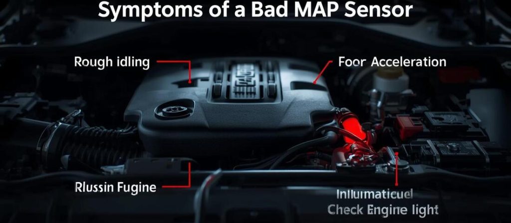
A MAP sensor can cause rough running, hesitation, poor acceleration, stalling and check-engine lights when its pressure signal is inaccurate. But replacing the sensor based only on a symptom or trouble code is a common diagnostic mistake.
The better approach is to test the MAP sensor and its circuit as a system.
You can often start with an OBD2 scanner and then use a multimeter or vacuum pump for additional testing. The exact voltage, pressure and test procedure vary by vehicle, so use the manufacturer’s specifications whenever available.
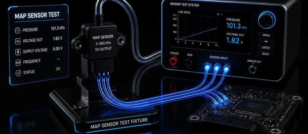
To test a MAP sensor:
- Scan for diagnostic trouble codes.
- Inspect the sensor, connector and wiring.
- Check MAP data with the key on and engine off.
- Check MAP data at warm idle.
- Watch how the reading responds to changing engine load.
- Verify the 5V reference and sensor ground when applicable.
- Check the MAP signal circuit with a multimeter.
- Use a vacuum pump when a direct sensor-response test is needed.
- Compare your results with the vehicle manufacturer’s specifications.
Don’t replace the MAP sensor until you’ve ruled out wiring, power, ground, connector, vacuum and intake problems.
Contents
- 1 What Does a MAP Sensor Do?
- 2 What You Need to Test a MAP Sensor
- 3 MAP Sensor Testing: Start With a Scan Tool
- 4 Test 1: Check MAP With the Key On, Engine Off
- 5 Test 2: Check MAP at Idle
- 6 Test 3: Check MAP Response to Throttle
- 7 Test 4: Check MAP Sensor Power
- 8 Test 5: Check MAP Sensor Ground
- 9 Test 6: Check MAP Signal With a Multimeter
- 10 Test 7: Test the MAP Sensor With a Vacuum Pump
- 11 How to Interpret MAP Sensor Readings
- 12 What Voltage Should a MAP Sensor Read?
- 13 What Should a MAP Sensor Read at Idle?
- 14 Common Diagnostic Trouble Codes (DTC)
- 15 MAP Sensor vs Vacuum Leak
- 16 MAP Sensor vs MAF Sensor
- 17 When Should You Replace the MAP Sensor?
- 18 Common MAP Sensor Testing Mistakes
- 19 FAQs About MAP Sensor Testing Guide
- 20 Final Verdict
What Does a MAP Sensor Do?
MAP stands for Manifold Absolute Pressure.
The sensor measures pressure inside the intake manifold and sends a signal to the engine computer.
The PCM/ECM uses MAP information to help determine engine load and control engine operation.
In simple terms:
The MAP sensor tells the computer how much pressure is present in the intake manifold.
At higher engine vacuum, manifold absolute pressure is lower.
When the throttle opens and engine load increases, manifold pressure rises toward atmospheric pressure.
That changing pressure is what makes the MAP sensor useful for diagnosis.
What You Need to Test a MAP Sensor
For basic testing:
- OBD2 scanner with live data
- Digital multimeter
- Vehicle wiring diagram
- Manufacturer service information
For more advanced testing:
- Hand vacuum pump
- Back-probe leads
- Oscilloscope
A scan tool is usually the best starting point because it lets you see what the PCM actually believes the MAP sensor is reporting.
MAP Sensor Testing: Start With a Scan Tool
Before touching the sensor, scan the vehicle.
Look for codes such as:
- P0105 — MAP/BARO circuit malfunction
- P0106 — MAP/BARO range/performance
- P0107 — MAP/BARO low input
- P0108 — MAP/BARO high input
- P0109 — MAP/BARO intermittent
These codes help narrow the diagnosis, but they don’t automatically prove that the MAP sensor is defective. P0106, for example, represents a range/performance problem and can require checking the sensor circuit and engine operating conditions.
Before clearing the code
Record:
- Freeze-frame data
- Engine RPM
- Coolant temperature
- MAP
- Engine load
- Throttle position
- Fuel trims
- Related codes
This information can tell you what the engine was doing when the fault occurred.
Test 1: Check MAP With the Key On, Engine Off
This is one of the most useful tests.
Turn the ignition on without starting the engine.
At this point, the intake manifold is not producing normal engine vacuum, so the MAP sensor should be reading pressure close to the current atmospheric pressure.
A useful cross-check is the BARO reading, if your scan tool displays it.
The MAP and BARO readings should generally be close under key-on/engine-off conditions, although exact tolerances depend on the vehicle.
One generic diagnostic reference recommends comparing MAP and BARO in this condition.
What you’re looking for
Normal:
MAP ≈ atmospheric pressure/BARO
Suspicious:
MAP is dramatically different from BARO with the engine off.
That can point toward:
- Sensor problem
- Wiring problem
- Reference/ground problem
- Incorrect data
- Vehicle-specific calibration issue
Don’t condemn the sensor from this test alone.

Test 2: Check MAP at Idle
Start the engine and allow it to reach normal operating temperature unless the manufacturer’s procedure says otherwise.
Watch the MAP value.
With the engine idling, the throttle is mostly closed and the engine normally creates substantial intake vacuum.
That means:
MAP pressure should fall significantly below atmospheric pressure.
For example, a generic naturally aspirated engine may show roughly 25–40 kPa absolute pressure at idle, but this is not a universal specification.
Engine design, altitude, camshaft timing, throttle condition and other factors can change the reading.
The important thing isn’t memorizing one number.
Ask:
Does the reading make sense for this engine’s operating condition?
Test 3: Check MAP Response to Throttle
This is one of the most valuable tests.
With the engine running, observe the MAP data while changing throttle position.
When the throttle opens quickly, manifold pressure should rise toward atmospheric pressure.
When the throttle closes again, manifold pressure should fall.
Engineer Fix describes this dynamic response as an important part of MAP diagnosis and notes that a rapid throttle change should produce a corresponding pressure response.
A healthy response should be:
- Fast
- Smooth
- Consistent
- Appropriate for engine load
A suspicious response may:
- Stay fixed
- Change very slowly
- Drop out
- Jump erratically
- Contradict throttle position and RPM
A graphing scan tool makes this much easier to see.
Test 4: Check MAP Sensor Power
If the scan data doesn’t make sense, move to electrical testing.
Many MAP sensors use a 5-volt reference circuit supplied by the PCM.
But don’t assume every vehicle uses the same wiring arrangement.
Use the vehicle-specific wiring diagram to identify:
- Reference circuit
- Ground
- Signal circuit
Then check the reference voltage according to the manufacturer’s procedure.
Some factory procedures specify approximately 5V; for example, one Dodge diagnostic procedure specifies a 4.5–5.5V range for its MAP reference circuit.
Important
Don’t apply battery voltage to a 5V reference circuit.
You can damage the PCM.

Test 5: Check MAP Sensor Ground
A missing or high-resistance sensor ground can make a perfectly good MAP sensor appear defective.
Check the ground using the manufacturer’s specified test.
Depending on the vehicle, this may involve:
- Voltage-drop testing
- Test-light testing
- Resistance testing
- Circuit integrity testing
A factory diagnostic procedure should take priority over a generic internet test.
Test 6: Check MAP Signal With a Multimeter
If the sensor uses a voltage-output circuit, you can monitor the signal with a digital multimeter.
The exact signal voltage depends on:
- Sensor design
- Atmospheric pressure
- Engine vacuum
- Vehicle calibration
A common MAP sensor design produces a higher signal voltage at higher manifold pressure and a lower voltage as vacuum increases.
But don’t use:
“4.5V = good”
or
“1.0V = bad”
as universal rules.
A generic MAP reference describes approximately 4.5V at atmospheric pressure and a decreasing signal as vacuum is applied, but the exact test values must be matched to the application.
Test 7: Test the MAP Sensor With a Vacuum Pump
A hand vacuum pump can provide a more controlled test.
The basic principle is simple:
Apply vacuum → MAP pressure should decrease → sensor signal should respond smoothly.
For a voltage-output sensor, the signal voltage will generally decrease as vacuum increases.
For example, a vehicle-specific diagnostic procedure may specify exact voltage changes at particular vacuum levels.
Don’t copy those values to another vehicle.
A GM-specific MAP procedure, for example, tests whether the signal voltage changes as vacuum is applied and separately verifies the sensor’s 5V supply and ground.
What indicates a problem?
A sensor becomes more suspicious if:
- Signal doesn’t change
- Signal jumps
- Signal drops out
- Signal doesn’t return correctly
- Sensor doesn’t hold the expected response
But first confirm:
- Correct power
- Correct ground
- Correct wiring
- Unblocked sensor port

How to Interpret MAP Sensor Readings
Don’t diagnose MAP sensors from a single number.
Instead, evaluate the reading in context.
| Condition | What you generally expect |
|---|---|
| Key on, engine off | MAP close to atmospheric pressure |
| Warm idle | MAP significantly below atmospheric pressure on a healthy naturally aspirated engine |
| Throttle opening | MAP rises |
| Throttle closing | MAP falls |
| Increasing engine load | MAP generally rises |
| Stable operating condition | MAP should remain reasonably stable |
These are diagnostic patterns, not universal specifications.
What Voltage Should a MAP Sensor Read?
There isn’t one universal answer.
Many common MAP sensors use a voltage signal that changes with manifold pressure, often within a range around the sensor’s reference voltage.
But the actual expected voltage depends on:
- Vehicle
- Engine
- Sensor
- Atmospheric pressure
- Engine vacuum
- Calibration
So the correct answer for The Car Buzz should be:
Use the manufacturer’s voltage specification for your exact vehicle rather than relying on a universal MAP voltage chart.
This is much safer and more technically accurate.
What Should a MAP Sensor Read at Idle?
Again, there isn’t one universal value.
A naturally aspirated engine at warm idle should normally show significantly lower absolute pressure than atmospheric pressure because the closed throttle creates intake vacuum.
A generic diagnostic source gives approximately 25–40 kPa as a typical warm-idle range, but this should be treated only as a rough diagnostic reference, not a pass/fail specification.
Turbocharged engines and unusual engine configurations require even more caution.

Common Diagnostic Trouble Codes (DTC)
| DTC Code | Code Description | Typical Electrical / Mechanical Fault |
| P0105 | MAP Circuit Malfunction | General circuit failure or loss of sensor communication |
| P0106 | MAP Range / Performance Problem | Signal is irrational compared to TPS/RPM (often a vacuum leak) |
| P0107 | MAP Circuit Low Input | Open signal circuit, short to ground, or unplugged connector |
| P0108 | MAP Circuit High Input | Short to 5V power, open ground wire, or disconnected vacuum line |
| P0109 | MAP Circuit Intermittent | Loose harness pin, corroded terminal, or cracked internal solder |
| P0068 | MAP / MAF / Throttle Correlation | MAP reading does not match throttle blade opening angle |
MAP Sensor vs Vacuum Leak
This is where the article should demonstrate real diagnostic expertise.
A vacuum leak can produce MAP-related symptoms without the MAP sensor being defective.
MAP sensor problem
You may find:
- Incorrect static reading
- Abnormal signal response
- Correct power/ground but incorrect output
- Signal dropout
- Sensor fails controlled vacuum test
Vacuum/intake problem
You may find:
- Abnormal idle
- Lean fuel trims
- Hissing
- Damaged vacuum hose
- Intake-manifold leak
- MAP reading that changes because actual manifold pressure is wrong
The key lesson
The MAP sensor reports manifold pressure. It doesn’t create the pressure.
That’s an excellent sentence to keep in the article.
MAP Sensor vs MAF Sensor
| MAP | MAF |
|---|---|
| Measures manifold absolute pressure | Measures incoming air mass |
| Used to estimate engine load | Directly measures airflow |
| Usually mounted on/near intake manifold | Usually mounted in intake tract |
| Pressure-based measurement | Airflow-based measurement |
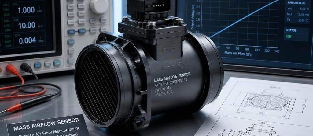
Some vehicles use both.
If you already have your Mass Airflow Sensor Testing Guide, this should be a prominent contextual internal link.
When Should You Replace the MAP Sensor?
Replace the sensor when testing provides enough evidence that the sensor itself is faulty.
Before replacement, verify:
- Correct reference voltage
- Correct ground
- Good connector
- Good signal circuit
- No obvious intake/vacuum problem
- Sensor response is outside specifications
Don’t replace the MAP sensor simply because:
- P0106 is stored
- The engine idles rough
- Fuel economy dropped
- The check-engine light is on
- The sensor looks dirty
The diagnosis should identify the failed component.
Common MAP Sensor Testing Mistakes
1. Using a universal voltage chart
MAP sensor specifications vary.
2. Ignoring atmospheric pressure
Altitude changes the key-on/engine-off MAP reading.
3. Testing only at idle
A sensor may look normal at one operating point and fail dynamically.
4. Ignoring the 5V reference
A missing reference can make a good sensor look bad.
5. Ignoring sensor ground
A bad ground can corrupt the signal.
6. Ignoring vacuum leaks
A real pressure problem can look like a sensor problem.
7. Replacing the sensor because of P0106
P0106 is a performance/rationality fault, not a guaranteed sensor failure.
8. Probing wires without a wiring diagram
Wrong connections can damage sensitive circuits.
FAQs About MAP Sensor Testing Guide
How do you test a MAP sensor?
Start by scanning for codes and checking MAP live data with the key on, engine off and with the engine running. Then verify the sensor’s power, ground and signal circuits. A vacuum pump can be used to test the sensor’s pressure response when appropriate.
What should a MAP sensor read with the engine off?
With the key on and engine off, MAP should generally be close to atmospheric pressure because the engine isn’t producing intake vacuum. Comparing MAP with the scan tool’s BARO value is useful when BARO data is available.
What should a MAP sensor read at idle?
A naturally aspirated engine should normally show significantly less absolute pressure than atmospheric pressure at warm idle. A rough generic range is 25–40 kPa, but the correct specification is vehicle-specific.
Can I test a MAP sensor with a multimeter?
Yes, if the sensor uses a voltage-output circuit. You can check its reference, ground and signal, but you need the vehicle-specific wiring diagram and specifications.
Can I test a MAP sensor without a scan tool?
Yes. A multimeter and appropriate vacuum pump can be used on many systems. However, a scan tool makes it much easier to evaluate the MAP reading in relation to RPM, throttle position and engine load.
Does P0106 mean the MAP sensor is bad?
No. P0106 indicates a MAP/BARO range or performance problem. Vacuum leaks, wiring faults, reference/ground problems and other engine conditions can cause it.
Final Verdict
The correct way to test a MAP sensor is not to look for one magic voltage.
Use a layered diagnosis:
Codes → visual inspection → KOEO MAP → idle MAP → dynamic response → power → ground → signal → vacuum test → vehicle specifications
If the sensor has correct power and ground but its output doesn’t respond correctly to controlled changes in manifold pressure, you have much stronger evidence that the sensor itself is faulty.
Diagnose the circuit before buying the part.