
This article was updated in August 28, 2026 with new products and information by Mark S. Taylor
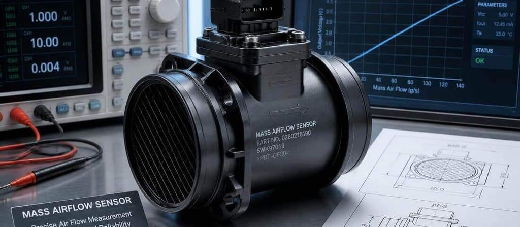
A mass airflow sensor, or MAF sensor, tells the engine computer how much air is entering the engine. When its reading is wrong, the engine can develop rough idle, hesitation, poor acceleration, stalling, poor fuel economy, or a check-engine light.
But don’t replace the MAF just because you have one of those symptoms—or even because you have a MAF-related trouble code.
The correct test is to verify the sensor’s power and ground, inspect the intake system, watch its live-data response, and compare the signal with the specifications for your particular vehicle.
There is no single voltage or grams-per-second reading that proves every MAF sensor is good or bad. MAF sensors can use different signal types, and their expected readings vary by vehicle and engine.
The easiest way to test a MAF sensor is with an OBD-II scan tool that can display live MAF data.
Start by:
- Scanning for trouble codes.
- Inspecting the air intake and MAF connector.
- Checking MAF power and ground.
- Watching the MAF reading at warm idle.
- Increasing engine speed and watching whether airflow rises smoothly.
- Comparing the readings with the manufacturer’s specifications.
- Checking fuel trims and other sensor data for plausibility.
- Using a multimeter or oscilloscope when the signal circuit needs further testing.
If the MAF signal is missing, erratic, or implausible after the power, ground, wiring, and intake system have been verified, the sensor becomes a much stronger suspect.
Contents
- 1 What Is a MAF Sensor?
- 2 Symptoms That Make MAF Testing Necessary
- 3 What You Need to Test a MAF Sensor
- 4 How to Test a MAF Sensor With a Scan Tool
- 5 How to Test a MAF Sensor With a Multimeter
- 6 Step 1: Identify the Sensor Type
- 7 Step 2: Check Power
- 8 Step 3: Check Ground
- 9 Step 4: Check the Signal
- 10 How to Test a Frequency-Type MAF
- 11 How to Test MAF Signal Response
- 12 How to Interpret MAF g/s Readings
- 13 Use Fuel Trims to Check MAF Plausibility
- 14 How to Tell a Bad MAF From a Vacuum Leak
- 15 How to Test a MAF With an Oscilloscope
- 16 MAF Sensor Codes: P0100–P0104
- 17 Should You Clean or Replace the MAF?
- 18 When Should You Replace the MAF?
- 19 Common MAF Testing Mistakes
- 19.1 1. Using a universal voltage chart
- 19.2 2. Testing the wrong wire
- 19.3 3. Ignoring the intake system
- 19.4 4. Looking only at idle g/s
- 19.5 5. Replacing the sensor because of P0101
- 19.6 6. Ignoring fuel trims
- 19.7 7. Cleaning the sensor with the wrong chemical
- 19.8 8. Using an inexpensive unverified replacement
- 20 FAQs About Mass Airflow Sensor Testing Guide
- 21 FINAL VERDICT
What Is a MAF Sensor?
The MAF sensor measures the mass of air entering the engine.
The engine computer uses that information to calculate fuel delivery and manage engine operation.
Most modern MAF sensors use a heated wire or film. As intake air moves across the sensing element, it changes the amount of energy needed to maintain the element at its controlled temperature. The electronics convert that information into a signal the engine computer can use.
Depending on the vehicle, the output may be:
- Analog voltage
- Frequency
- A digitally processed signal
- A scan-tool value such as grams per second
That’s why you should identify the sensor type before connecting a meter and assuming which wire or test value is correct.
Symptoms That Make MAF Testing Necessary
A MAF problem can cause:
- Rough idle
- Hesitation
- Poor acceleration
- Stalling
- Poor fuel economy
- Hard starting
- Rich or lean running
- Check-engine light
- Reduced engine performance
But these symptoms aren’t unique to the MAF.
For example, a vacuum leak after the MAF can allow unmetered air into the engine and produce lean fuel trims, hesitation, and poor idle even when the MAF itself is working correctly.
So the goal isn’t:
“Find a symptom that matches a bad MAF.”
The goal is:
Prove whether the MAF signal is accurate and plausible.

What You Need to Test a MAF Sensor
Basic testing
- OBD-II scan tool
- Digital multimeter
- Vehicle wiring diagram
- Service information
Advanced testing
- Oscilloscope
- Back-probe leads
- Current probe, depending on the sensor/system
You don’t necessarily need every tool.
For many DIYers, a capable scan tool is the best starting point because it allows you to see the MAF’s actual reported airflow without guessing at individual wires.
How to Test a MAF Sensor With a Scan Tool
Step 1: Scan for Trouble Codes
Connect the scan tool and check for stored and pending codes.
Common MAF-related codes include:
- P0100 — MAF circuit malfunction
- P0101 — MAF circuit range/performance
- P0102 — MAF circuit low input
- P0103 — MAF circuit high input
- P0104 — MAF circuit intermittent
A code helps direct the diagnosis, but it doesn’t automatically identify the failed component.
For example, a range/performance code can result from an airflow problem elsewhere in the system.
Step 2: Check the MAF Live Data
Open the scan tool’s live-data or data-list function.
Look for a parameter labeled something like:
- MAF
- MAFS
- Air Flow
- Air Mass
- Mass Air Flow Rate
The display may use:
- g/s
- lb/min
- voltage
- Hz
- another manufacturer-specific unit
Step 3: Check the MAF at Warm Idle
Allow the engine to reach normal operating temperature unless the manufacturer’s procedure specifies otherwise.
Watch the MAF reading.
You’re looking for a reading that is:
- Stable
- Plausible for the engine
- Consistent with engine operating conditions
ALLDATA’s technical testing material gives 2–7 g/s at idle as an example range and 15–25 g/s at 2,500 RPM, but specifically notes that actual specifications depend on engine size and manufacturer.
Important:
Don’t publish those numbers as:
“Every good MAF must read 2–7 g/s.”
That’s incorrect.
Use the manufacturer’s specifications whenever available.
Step 4: Increase Engine Speed
Slowly increase engine RPM while watching the MAF reading.
A healthy MAF should respond to increasing airflow.
The reading should generally increase smoothly rather than:
- Stay frozen
- Drop unexpectedly
- Jump randomly
- Show obvious dropouts
ALLDATA recommends graphing MAF output over an increasing RPM range because the sensor should demonstrate a steady, progressive response.
This is often more useful than staring at one idle number.

How to Test a MAF Sensor With a Multimeter
A multimeter can be useful, but don’t start probing wires until you know what each wire does.
MAF connectors can contain:
- Power
- Ground
- Signal
- Intake-air-temperature circuits
- Other sensor/control circuits
Use the wiring diagram for your exact vehicle.
Engineer Fix similarly recommends identifying the vehicle-specific wiring diagram before probing the connector because incorrectly identifying a circuit can lead to an incorrect diagnosis or electrical damage.
Step 1: Identify the Sensor Type
Determine whether your MAF produces:
- Variable voltage
- Frequency
- Another digital/processed signal
A standard DC-voltage test is not appropriate for every MAF design.
Frequency-output sensors require frequency-capable equipment or an oscilloscope.
Step 2: Check Power
With the appropriate ignition state specified by the vehicle procedure, verify the sensor’s power supply.
Depending on the design, the sensor may use a battery-voltage supply or a regulated reference.
Do not assume every MAF uses 12 volts.
Step 3: Check Ground
A poor ground can make a good sensor look defective.
Check the ground circuit using the manufacturer’s specified test method.
A voltage-drop test can be particularly useful when you suspect a high-resistance ground.
Step 4: Check the Signal
For a voltage-output MAF, monitor the signal while the engine runs.
The important question isn’t:
“Does it read exactly 1.0 volt?”
The better question is:
Does the signal change smoothly and plausibly as airflow changes?
Some hot-wire MAFs may produce a low signal voltage at idle and a higher signal as airflow increases, but the actual voltage range varies by sensor and application.

How to Test a Frequency-Type MAF
Some MAF sensors communicate airflow as a frequency signal.
In that case, the signal is measured in Hertz (Hz) rather than simply looking for a fixed voltage.
As airflow increases, the signal frequency should respond according to the sensor’s design.
A frequency meter or oscilloscope is better suited to this test.
If you only have a basic multimeter that cannot accurately measure the signal type used by your MAF, don’t improvise a voltage test.
Use the correct equipment or rely on scan data.
How to Test MAF Signal Response
This is one of the most important parts of the diagnosis.
A sensor can produce a believable idle value and still have a problem at higher airflow.
Look for:
Good response
- Smooth increase
- No sudden dropouts
- No unexplained spikes
- Consistent response to changing RPM/load
Suspicious response
- Flat signal
- Sudden dropouts
- Erratic spikes
- Delayed response
- Signal doesn’t match engine operating conditions
A graphing scan tool or oscilloscope makes these problems much easier to see.
How to Interpret MAF g/s Readings
MAF readings are highly dependent on:
- Engine displacement
- Engine speed
- Engine load
- Atmospheric pressure
- Forced induction
- Engine design
- Sensor calibration
So don’t use a universal table like:
2.0-liter = exactly X g/s.
That’s too simplistic.
ALLDATA’s technical material provides example values but emphasizes that manufacturer-specific PID specifications should be used for diagnosis.
A better diagnostic question
Ask:
Does the MAF reading make sense for what the engine is doing?
For example:
If engine load increases dramatically but the MAF reading barely changes, that deserves investigation.

Use Fuel Trims to Check MAF Plausibility
Fuel trims can provide another piece of evidence.
Look at:
- STFT — Short-Term Fuel Trim
- LTFT — Long-Term Fuel Trim
If the engine computer is consistently adding fuel because it believes the mixture is lean, investigate why.
Possible causes include:
- Under-reporting MAF
- Vacuum leak
- Intake leak
- Low fuel pressure
- Injector problem
- Exhaust leak affecting oxygen-sensor readings
- Other engine-management faults
This is why fuel trims should support the MAF diagnosis rather than automatically condemn the sensor.
How to Tell a Bad MAF From a Vacuum Leak
This is one of the most important diagnostic distinctions.
Possible MAF problem
The MAF signal is implausible, unstable, or doesn’t respond correctly after the electrical supply and intake system have been verified.
Possible intake leak
The MAF reports the air entering the engine correctly, but additional unmetered air enters downstream of the sensor.
That can create:
- Positive fuel trims
- Rough idle
- Hesitation
- Lean codes
Diagnostic clue
If fuel trims are much worse at idle and improve as RPM increases, an intake/vacuum leak deserves investigation.
Don’t use that pattern as absolute proof, but it can help direct testing.
How to Test a MAF With an Oscilloscope
An oscilloscope becomes useful when you need to see the shape and stability of the signal, not merely its average value.
It can reveal:
- Dropouts
- Electrical noise
- Irregular transitions
- Intermittent faults
- Signal distortion
- Frequency changes
For a frequency-output MAF, the scope can also show how the signal changes as airflow increases.
This is especially valuable for intermittent problems that a scan tool may smooth or miss.
MAF Sensor Codes: P0100–P0104
| Code | General meaning |
|---|---|
| P0100 | MAF circuit malfunction |
| P0101 | MAF circuit range/performance |
| P0102 | MAF circuit low input |
| P0103 | MAF circuit high input |
| P0104 | MAF circuit intermittent |
These are useful diagnostic clues, not automatic replacement instructions.
For example, P0101 can result from a MAF signal that doesn’t make sense compared with other engine operating parameters.
The technician still needs to determine why.
Should You Clean or Replace the MAF?
Don’t automatically replace a MAF because it’s dirty.
If contamination is suspected and the sensor manufacturer’s procedure permits cleaning, use a dedicated MAF sensor cleaner and follow the product/vehicle instructions.
Do not touch a delicate sensing element unless the manufacturer specifically allows it.
Don’t substitute aggressive solvents such as brake cleaner or carburetor cleaner unless the manufacturer explicitly specifies compatibility.
A contaminated sensor may improve after proper cleaning, but cleaning won’t fix:
- Broken wiring
- Bad power supply
- Bad ground
- Internal electronics failure
- Damaged sensing element
- Intake leaks
When Should You Replace the MAF?
Replacement makes sense when testing establishes that:
- The sensor has proper power and ground
- Wiring and connector are good
- Intake leaks and other major causes have been ruled out
- The sensor’s signal is missing, implausible, or unstable
- The sensor fails the vehicle’s specified test procedure
Don’t replace it simply because:
- The engine idles rough
- Fuel economy dropped
- P0101 is stored
- The sensor looks dirty
Common MAF Testing Mistakes
1. Using a universal voltage chart
MAF sensor outputs vary.
2. Testing the wrong wire
Always identify the circuit using the vehicle-specific wiring diagram.
3. Ignoring the intake system
A cracked intake boot can mimic a MAF problem.
4. Looking only at idle g/s
A MAF can behave normally at idle and fail under increased airflow.
5. Replacing the sensor because of P0101
P0101 is a performance/range clue, not a parts-order instruction.
6. Ignoring fuel trims
Fuel trims can provide valuable context.
7. Cleaning the sensor with the wrong chemical
The sensing element can be damaged.
8. Using an inexpensive unverified replacement
MAF calibration matters. A sensor that physically fits isn’t necessarily correctly calibrated for the vehicle.
FAQs About Mass Airflow Sensor Testing Guide
How do I test a mass airflow sensor?
Start with a scan for codes, inspect the intake and connector, verify power and ground, then watch MAF live data at idle and while engine speed increases. Compare the readings with vehicle-specific specifications. If necessary, test the sensor’s voltage or frequency signal with appropriate equipment.
What should a MAF sensor read at idle?
There is no single correct value for every vehicle. MAF readings depend on engine size, design, operating conditions, and sensor calibration. Some technical references use 2–7 g/s as an example range for certain engines, but manufacturer specifications should take priority.
Can I test a MAF sensor with a multimeter?
Yes, on many vehicles, but the exact test depends on the MAF’s signal type. A multimeter can check power, ground, and voltage signals. Frequency-output sensors may require frequency measurement or an oscilloscope.
How do I know if my MAF sensor is bad?
You need more than one symptom or code. Confirm the intake system, wiring, power and ground first, then evaluate the MAF signal and live data against the vehicle’s specifications.
Can a dirty MAF cause a lean code?
It can, but a lean code does not prove the MAF is dirty or defective. Vacuum leaks, fuel-delivery problems and other engine faults can also create lean conditions.
FINAL VERDICT
The best MAF diagnosis isn’t based on one magic number.
Test the system.
Check:
Intake → codes → wiring → power/ground → live data → signal response → fuel trims → vehicle specifications
If the sensor still fails after those checks, replacement becomes a defensible diagnosis rather than a guess.