
This article was updated in September 15, 2026 with new products and information by Mark S. Taylor
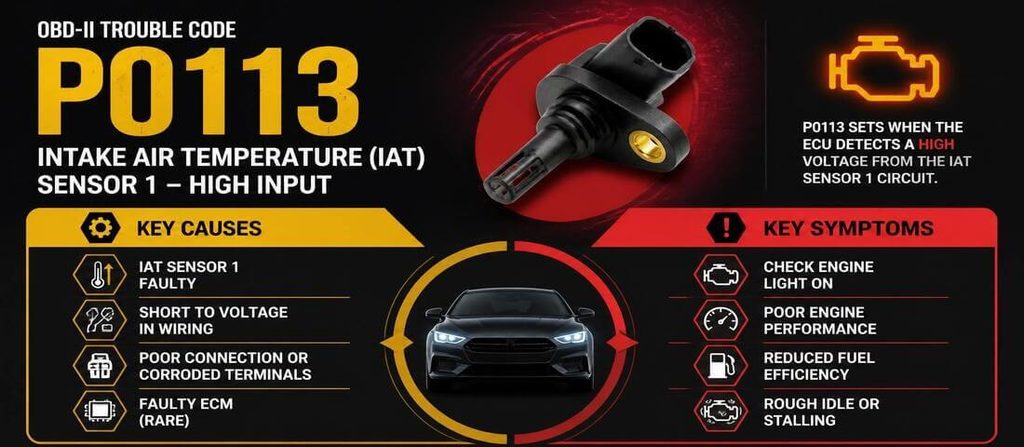
If your check engine light is on and your scanner shows P0113 code, the problem is related to the intake air temperature (IAT) sensor circuit.
But there’s an important distinction: P0113 does not automatically mean you need a new IAT sensor.
The code means the engine computer is detecting a high signal from the Intake Air Temperature Sensor 1 circuit. That can happen because of a failed sensor, but an open wire, damaged connector, poor electrical connection, or other circuit problem can create the same fault.
The right repair is to test the IAT circuit before replacing parts.
Contents
- 1 What Does P0113 Mean?
- 2 What Does “Circuit High” Mean?
- 3 P0113 Symptoms
- 4 Common Causes of P0113
- 5 How to Diagnose P0113
- 5.1 Step 1: Scan for All Trouble Codes
- 5.2 Step 2: Check the IAT Reading on the Scan Tool
- 5.3 Step 3: Inspect the IAT Sensor
- 5.4 Step 4: Inspect the Connector
- 5.5 Step 5: Inspect the Wiring
- 5.6 Step 6: Test the Sensor
- 5.7 Step 7: Test the Wiring
- 5.8 Step 8: Check the Reference/Supply Circuit
- 5.9 Step 9: Check for Technical Service Bulletins
- 6 How to Fix P0113
- 7 Does P0113 Mean the IAT Sensor Is Bad?
- 8 Can You Drive With P0113?
- 9 P0113 vs P0112
- 10 P0113 Repair Cost
- 11 Common P0113 Diagnostic Mistakes
- 12 FAQs About P0113 Code: Causes, Symptoms & Fixes
- 13 Final Verdict
Quick Answer: What Causes P0113?
The most common causes of P0113 include:
- Failed intake air temperature sensor
- Broken IAT signal wire
- Damaged or disconnected connector
- Corroded connector terminals
- Wiring open circuit
- Shorted or damaged harness
- Contaminated or physically damaged sensor
- Incorrectly installed sensor
- IAT sensor integrated into a faulty MAF or MAP assembly
- Rarely, a PCM or wiring-reference problem
The best way to fix P0113 is to inspect the IAT sensor and connector first, then test the wiring and sensor according to the vehicle manufacturer’s specifications.
What Does P0113 Mean?
P0113 stands for:
Intake Air Temperature Sensor 1 Circuit High
The IAT sensor measures the temperature of the air entering the engine.
The PCM uses that temperature information along with other engine data to help determine appropriate fuel and ignition strategies. HELLA explains that IAT sensor voltage changes with temperature and that the engine control unit uses the signal to influence mixture formation and ignition timing.
The exact sensor design varies by vehicle.
On some engines, the IAT is a separate sensor installed in the intake tract.
On others, the IAT sensor is integrated into a MAF or MAP sensor assembly.
That difference matters because you may not be able to replace the IAT separately on every vehicle.
What Does “Circuit High” Mean?
This part causes a lot of confusion.
“Circuit high” refers to the electrical signal being higher than the PCM expects. It does not necessarily mean the intake air temperature itself is extremely high.
For an NTC-style IAT sensor, resistance normally decreases as temperature increases. Because of the sensor’s voltage-divider circuit, a high signal voltage can correspond to a very low or implausible temperature reading depending on the circuit design.
In other words, don’t interpret P0113 as:
“The engine is getting too much hot air.”
Interpret it as:
“The PCM is seeing an abnormally high electrical signal from the IAT circuit.”
One OEM diagnostic table, for example, lists P0113 when IAT signal voltage exceeds 4.50 V. That is an example of a manufacturer-specific threshold—not a universal P0113 voltage specification.
P0113 Symptoms
P0113 can produce different symptoms depending on the vehicle and the actual fault.
Possible symptoms include:
- Check engine light
- Difficult starting
- Rough running
- Poor acceleration
- Reduced engine power
- Increased fuel consumption
- Poor throttle response
- Engine running rich or lean under certain conditions
- Reduced emissions performance
- Emergency or substitute-value operating strategy
HELLA lists starting problems, reduced engine power and increased fuel consumption among possible effects of an IAT sensor fault.
Some vehicles may show very few noticeable symptoms besides the check engine light.
Common Causes of P0113
1. Failed IAT Sensor
The sensor itself can fail internally.
Electronic faults, physical damage or contamination can change the sensor’s electrical response.
However, don’t replace it simply because P0113 is stored.
Test it first.
2. Broken IAT Signal Wire
An open circuit can cause the PCM to see a high signal.
Inspect the harness near the sensor carefully.
Look for:
- Broken wires
- Chafing
- Stretched wiring
- Melted insulation
- Previous repair work
- Rodent damage
3. Damaged IAT Connector
A connector can cause P0113 even when the sensor is good.
Check for:
- Loose terminals
- Bent pins
- Corrosion
- Water intrusion
- Broken locking tabs
- Terminals pushed backward inside the connector
4. Wiring Strain
Don’t overlook mechanical stress on the harness.
FCA issued a service bulletin for certain 2015 Jeep Renegade and 2016 Fiat 500X models with the 2.4L engine where wiring strain at the IAT connector could cause P0113. The documented repair involved adding a jumper harness to reduce the strain.
That’s a good example of why checking vehicle-specific service information can be more valuable than immediately buying a sensor.
5. Corrosion or Poor Electrical Contact
Even a small amount of corrosion can interfere with a low-current sensor circuit.
Inspect both sides of the connector where possible.
6. Contaminated Sensor
Dirt or deposits on the sensor can affect its ability to accurately measure intake-air temperature.
HELLA lists a dirty sensor tip as one possible cause of IAT sensor failure.
7. IAT Integrated Into Another Sensor
Some vehicles combine the IAT sensor with another component.
For example, the intake manifold pressure sensor may contain an integrated IAT element.
In other applications, the IAT is incorporated into the MAF assembly.
So before ordering a separate IAT sensor, verify how your particular engine is configured.
8. PCM or Reference-Circuit Problem
A PCM fault is possible but should be considered late in the diagnosis.
Don’t condemn the PCM before proving the sensor, connector, power/reference circuit and wiring are good.

How to Diagnose P0113
A good P0113 diagnosis starts with the electrical circuit, not the parts catalog.
Step 1: Scan for All Trouble Codes
Use an OBD-II scanner to record all stored and pending codes.
Don’t focus on P0113 alone.
Other sensor or engine-management codes may provide important clues.
Save the freeze-frame information if your scanner supports it.
Step 2: Check the IAT Reading on the Scan Tool
Look at the reported intake-air temperature.
A clearly implausible reading can provide an immediate clue.
For example, if the engine has been sitting overnight and the IAT reading is dramatically different from the surrounding air temperature, investigate the IAT circuit.
However, don’t use a generic temperature number as a universal specification.
Compare the reading with the manufacturer’s diagnostic information and the vehicle’s actual conditions.
Step 3: Inspect the IAT Sensor
Locate the sensor using the vehicle’s service information.
Check for:
- Physical damage
- Contamination
- Loose installation
- Broken housing
- Damaged sensing element
If the sensor is integrated into another component, inspect that assembly instead.
Step 4: Inspect the Connector
Disconnect the connector according to the manufacturer’s procedure.
Look carefully for:
- Corrosion
- Bent pins
- Loose terminals
- Broken locks
- Water
- Oil contamination
- Terminals pushed out of position
A connector that looks fine from the outside can still have a poor terminal connection.
Step 5: Inspect the Wiring
Follow the harness back from the IAT sensor.
Look for areas where the harness:
- Rubs against brackets
- Passes near hot components
- Has been repaired previously
- Is stretched tightly
- Has been pinched
- Has damaged insulation
Pay particular attention to areas where the harness moves with engine vibration.
Step 6: Test the Sensor
An IAT sensor is generally a temperature-dependent resistor.
On many applications it uses an NTC thermistor, meaning resistance decreases as temperature increases.
The exact resistance-to-temperature specification is vehicle-specific.
Use the manufacturer’s chart rather than a generic internet resistance value.
HELLA’s diagnostic procedure recommends measuring sensor resistance at a known temperature and comparing the result with the appropriate reference specification.
Step 7: Test the Wiring
If the sensor tests correctly, move to the circuit.
Depending on the vehicle, testing may include:
- Continuity
- Short-to-ground testing
- Short-to-voltage testing
- Reference/supply voltage
- Signal-circuit testing
- Terminal tension
Use the vehicle’s wiring diagram for pin identification.
Do not assume every IAT connector has the same pinout.
Step 8: Check the Reference/Supply Circuit
Many IAT circuits operate as part of a voltage-divider arrangement.
A commonly encountered design uses a 5-volt reference through the control circuit, but the exact architecture varies by vehicle.
HELLA gives approximately 5 V as an example reference during sensor testing while emphasizing the need to follow manufacturer-specific specifications.
Don’t apply a generic 5-volt rule to every vehicle without checking its wiring diagram.
Step 9: Check for Technical Service Bulletins
Search the vehicle’s:
- Year
- Make
- Model
- Engine
- P0113
Some vehicles have known harness, connector or software issues.
As the FCA example demonstrates, the root cause can sometimes be a known wiring problem rather than a failed sensor.

How to Fix P0113
The correct repair depends on what testing finds.
Fix 1: Repair the Wiring
If the IAT harness is broken, damaged or shorted, repair it using the manufacturer’s recommended wiring-repair procedure.
Don’t simply twist wires together and wrap them with electrical tape.
A poor repair can create intermittent problems that are harder to diagnose later.
Fix 2: Repair or Replace the Connector
If terminals are damaged or corroded, repair or replace the connector as required.
Terminal tension is important.
A connector can look plugged in while still making a poor electrical connection.
Fix 3: Replace the IAT Sensor
Replace the sensor when testing confirms that it is outside the manufacturer’s specifications or otherwise defective.
Use the correct sensor for the application.
If the IAT is integrated into a MAF or MAP sensor, the entire assembly may need to be replaced depending on the design.
Fix 4: Clean a Contaminated Sensor
If contamination is the confirmed cause and the manufacturer permits cleaning, use the appropriate cleaning procedure.
Don’t scrape or physically damage the sensing element.
If the sensor remains inaccurate after cleaning, replacement may be necessary.
Fix 5: Repair the Known Vehicle-Specific Problem
If a manufacturer bulletin identifies a known wiring or connector problem, follow that repair procedure.
For example, the FCA bulletin mentioned earlier specifies a jumper-harness repair for certain applications affected by IAT wiring strain.
Fix 6: Address a PCM/Circuit Problem
Only consider PCM-related repairs after the sensor and wiring have been properly tested.
A PCM should never be the first part you replace for P0113.
Does P0113 Mean the IAT Sensor Is Bad?
No.
This is the most important diagnostic point.
P0113 identifies a high electrical signal in the IAT circuit.
The sensor may be defective, but the same result can occur because of:
- Open wiring
- Connector problems
- Corrosion
- Harness damage
- Incorrect installation
- Integrated sensor failure
- Other circuit problems
HELLA’s IAT troubleshooting procedure specifically calls for checking the sensor wiring, connector and sensor for proper connection, breaks and corrosion before moving through electrical testing.
Diagnose the circuit. Don’t diagnose the part name.
Can You Drive With P0113?
Usually, P0113 is not an immediate mechanical emergency by itself.
However, you should avoid treating the code as harmless if the engine is:
- Running very poorly
- Stalling
- Difficult to start
- Losing significant power
- Running excessively rich
- Producing unusual exhaust smoke
- Showing additional serious trouble codes
The IAT signal contributes to engine-management calculations, so a false temperature input can affect drivability and fuel control.
If the vehicle is running normally apart from the warning light, arrange diagnosis rather than continuing indefinitely with the fault unresolved.
P0113 vs P0112
These codes are easy to confuse.
| Code | Meaning |
|---|---|
| P0111 | IAT Sensor 1 Circuit Range/Performance |
| P0112 | IAT Sensor 1 Circuit Low |
| P0113 | IAT Sensor 1 Circuit High |
| P0114 | IAT Sensor 1 Circuit Intermittent |
The important distinction is that P0113 indicates a high circuit signal, while P0112 indicates a low circuit signal.
That doesn’t mean the intake air is necessarily hot or cold. The codes describe the electrical behavior detected by the PCM.
P0113 Repair Cost
The cost depends heavily on the actual failure.
| Repair | Relative cost |
|---|---|
| Connector inspection/cleaning | Low |
| IAT sensor replacement | Low to moderate |
| Wiring repair | Low to moderate |
| Connector replacement | Low to moderate |
| Integrated MAF/MAP sensor replacement | Moderate |
| Harness diagnosis | Moderate |
| PCM-related repair | Potentially high |
Don’t use a generic sensor price as a diagnosis.
The sensor may be inexpensive while the actual problem is a damaged harness that requires diagnostic and wiring-repair labor.
Common P0113 Diagnostic Mistakes
Replacing the sensor immediately
This is the biggest mistake.
P0113 is a circuit-high code, not a “replace the sensor” command.
Assuming “high” means hot intake air
It doesn’t.
The code refers to the electrical signal.
Ignoring the connector
A damaged terminal can cause the same symptoms as a failed sensor.
Using generic resistance specifications
Temperature sensors vary.
Use the correct temperature/resistance chart for the vehicle.
Probing the wrong terminals
Always identify pins using the correct wiring diagram.
Replacing the PCM too early
Prove the sensor and wiring are good before blaming the control module.
Ignoring vehicle-specific bulletins
A known wiring issue can turn a difficult diagnosis into a straightforward repair.
FAQs About P0113 Code: Causes, Symptoms & Fixes
What is the most common cause of P0113?
Common causes include an IAT sensor problem, open or damaged wiring, connector faults and poor electrical connections. The exact cause varies by vehicle.
Can a bad IAT sensor cause P0113?
Yes. A defective IAT sensor can produce the high signal that triggers P0113.
Can wiring cause P0113?
Yes. An open or damaged circuit can cause the PCM to detect an abnormally high IAT signal.
Can a dirty IAT sensor cause P0113?
Contamination can affect IAT sensor operation, although the exact effect depends on the sensor design and fault condition.
Is P0113 serious?
Usually it is not an immediate engine-damage emergency, but it can affect fuel control, starting and drivability. It should be diagnosed rather than ignored.
Where is the IAT sensor located?
Location varies. It may be installed in the intake duct, airbox, intake manifold or integrated into a MAF or MAP sensor assembly.
Final Verdict
P0113 means the PCM is detecting a high electrical signal from the Intake Air Temperature Sensor 1 circuit.
The cause may be a bad IAT sensor, but it could just as easily be a broken wire, damaged connector, corrosion, harness problem or an IAT sensor integrated into another component.
The smartest diagnostic order is:
Scan → check live IAT data → inspect sensor → inspect connector → inspect wiring → test sensor → test circuit → check TSBs → replace the confirmed faulty component.
The key takeaway is simple:
P0113 is a circuit diagnosis, not a parts-replacement diagnosis.