
This article was updated in July 18, 2026 with new products and information by Mark S. Taylor
Wiring a car amplifier isn’t inherently complicated, but the entire process leaves absolute zero room for mechanical guessing. Get the primary power wire gauge wrong, and you will suffer from an aggressively dimming system or a melted wire insulation jacket burning under your interior carpet. Get the chassis ground wrong, and you will instantly introduce a high-pitched ground loop alternator whine that perfectly follows your engine’s RPM cycles.
Every successful amplifier installation comes down to executing five distinct connections in an exact, non-negotiable structural sequence: Power, Ground, Remote Turn-On, RCA Signal inputs, and Speaker Wiring. Car amplifiers do not include these heavy-gauge delivery lines out of the factory box. In this comprehensive workshop guide, we will break down the precise thermodynamic math required to size your wire gauge, outline a step-by-step routing layout, and map out the definitive troubleshooting matrix to eliminate induced electrical noise.

Contents
- 1 The 5 Core Amplifier Connections
- 2 US Wire Gauge (AWG) Sizing Matrix
- 3 Safety & Maintenance Tips
- 4 Troubleshooting: Amp Won’t Turn On or Sounds Wrong
- 5 FAQs About How to Wire a Car Amp
- 5.1 Where exactly should the fuse go, and what size?
- 5.2 Why won’t my amp turn on even though it’s wired correctly?
- 5.3 Can I ground the amp to any metal in the car?
- 5.4 Do I need a separate wiring kit for each amp if I’m running two?
- 5.5 What’s the difference between RMS and peak/max power, and why does it matter for wiring?
- 6 The Bottom Line
The 5 Core Amplifier Connections
To complete a clean installation loop, you must run five individual paths without letting your power lines compromise your low-voltage audio signals:
- Primary Power Lead: Delivers high-amperage current directly from the positive (+) battery terminal under the hood to the amplifier’s input block.
- Chassis Ground: Completes the electrical circuit by bonding the amplifier’s ground block to the bare, unpainted structural steel of the vehicle frame.
- Remote Turn-On (REM): A low-current, switched 12V signal wire that commands the amplifier to wake up only when the car’s head unit or ignition cycles on.
- RCA Preamp Cables: Carry the low-level analog audio voltage signal from the radio outputs to the amplifier’s clean inputs.
- Speaker Output Wiring: Transmits the high-voltage amplified audio signal out from the amplifier directly into your aftermarket speakers or subwoofer coils.
Step 1: Calculating Your Wire Gauge Sizing
Sizing your power cable to your amplifier’s maximum “Peak Power” branding is the fastest way to undersize your system. You must size your delivery infrastructure explicitly around the amplifier’s true RMS (Continuous) Power rating and the architecture of its circuit design.
Use these technician formulas to calculate your system’s actual maximum current draw:
- Class D Amplifiers (High-Efficiency Subwoofer Amps):$$\text{Current Draw (Amps)} \approx \frac{\text{Total RMS Wattage}}{13.8 \times 0.75}$$
- Class AB Amplifiers (Traditional Full-Range Speaker Amps):$$\text{Current Draw (Amps)} \approx \frac{\text{Total RMS Wattage}}{13.8 \times 0.50}$$
Mechanic Rule of Thumb: If you cannot verify your amplifier’s explicit circuit classification, always default to the conservative Class AB formula to ensure your power lines remain robustly oversized.
US Wire Gauge (AWG) Sizing Matrix
(Based on a standard 16 to 20-foot run from the front engine bay to the rear trunk area)
| Amplifier True RMS Power | Calculated Current Draw | Recommended Pure Copper Wire Gauge |
| Up to 150W RMS | ~20 Amps | 10-Gauge AWG |
| 150W – 300W RMS | ~40 Amps | 8-Gauge AWG |
| 300W – 600W RMS | ~80 Amps | 4-Gauge AWG |
| 600W – 1,200W RMS | ~145 Amps | 1/0-Gauge (Ought-Gauge) AWG |
| 1,200W+ RMS | 175+ Amps | Dual 1/0-Gauge or 4/0-Gauge Runs |
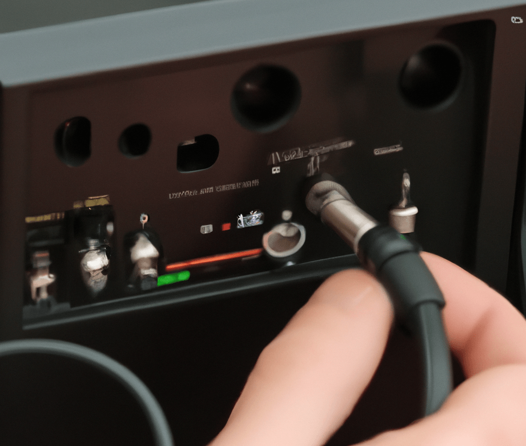
Step 2: Planning and Isolating Your Wire Runs
Before cutting a single foot of expensive copper wire, plan your path to eliminate electromagnetic interference (EMI).
The Separation Protocol: Never run your high-amperage main power cable down the same side of the vehicle as your low-voltage RCA signal lines or factory antenna leads. The heavy current cycles sweeping through the power wire will induce an electrical hum directly into the audio paths. Always run your main power cable down the driver-side doorsills, and route your RCA cables and remote turn-on line down the passenger-side floorboards.
Step 3: Installing the Inline Main Power Fuse
An inline fuse is engineered explicitly to protect the vehicle from burning to the ground if the primary cable chafes against bare metal and shorts out. It does not protect the amplifier itself (the amp has its own small fuses on the rear panel).
1. Decouple the Negative Battery Cable: 2 min.
Loosen the negative (-) ground terminal clamp on your car battery under the hood and lift it completely off the post. This eliminates all risk of short-circuits or dangerous arcing while handling live wires inside the cabin.
2. Position the Fuse Block Near the Source: 5 min.
Mount your inline main fuse holder within 18 inches of the positive (+) battery terminal. Leaving a long stretch of unfused wire running from the battery to a distant fender wall creates a massive fire risk if that specific zone ever shorts against the metal chassis during a collision.
3. Route Through the Firewall Grommet: 10 min.
Locate a factory rubber firewall grommet behind the dashboard. Never drill a bare hole through the metal firewall without inserting a rubber protective grommet; the sharp steel edges will slice through your wire insulation within weeks. Pull the power wire through and route it under the doorsill plastic trim to the amplifier location.
4. Leave the Fuse Core Open: 2 min.
Crucial: Keep the main inline fuse completely out of the holder until the entire installation is complete. This keeps the massive power line 100% dead while your hands are handling downstream amplifier terminal blocks.
Step 4: Mastering the Chassis Ground Connection
A loose, poorly isolated, or corroded ground connection is responsible for 85% of all amplifier malfunctions, thermal protect loops, and ground loop alternator whines.
- Keep it Brief: Locate a structural metal chassis point within 18 inches of the amplifier. A long ground wire acts like an antenna for electrical noise and raises circuit resistance.
- Scrape to Bare Metal: Use sandpaper, a wire wheel, or a grinding bit to completely strip away all factory paint, primer, and surface rust from your target metal spot until you expose a flat circle of shiny, bare steel. Paint acts as an electrical insulator and destroys ground continuity.
- Secure and Seal: Crimp a heavy-duty ring terminal onto your ground wire. Secure it tightly to the bare steel using a solid bolt or a heavy self-tapping screw. Once tightened down, spray a thin layer of clear protective paint or spread dielectric grease over the junction to block future oxidation without disrupting the core contact.
Step 5: Terminating Remote Signal and Audio Lines
- Switched 12V Trigger (REM): Locate the blue or blue/white wire on your aftermarket head unit wire harness harness. Connect your thin remote wire to this output using a crimped butt connector. If you are integrating into a factory OEM radio that lacks a remote trigger line, you must splice your wire into a switched accessory circuit inside the fuse box that only reads 12V when the ignition key turns on.
- RCA & Impedance Integrity: Snap your premium shielded RCA cables into the preamp outputs. At the amplifier end, run your speaker wires directly to your subwoofers or full-range speakers. Always double-check your speakers’ final wiring resistance (Ohmic Load) using a digital multimeter before plugging them in. Forcing a 2-Ohm load onto an amplifier that is only stable down to 4 Ohms will trigger rapid thermal shutdown and destroy the output transistors.

Safety & Maintenance Tips
- Always disconnect the negative battery terminal before starting any wiring work and before making any changes to an existing install.
- Never skip the inline fuse, and never fuse it near the amp instead of near the battery — the fuse’s job is to protect the full length of wire, and an unprotected run is a fire risk if it ever shorts against the chassis.
- Recheck all crimped connections after the first week of driving. Vibration loosens crimps that felt tight on install day; a loose crimp is a common cause of an intermittent connection that shows up weeks later.
- Inspect the ground point every six months to a year, especially in climates with road salt — corrosion rebuilds on bare metal over time and will gradually degrade a ground that tested fine at install.
- Keep the amp itself in a location with airflow. Amps generate real heat under load; mounting one in a sealed, carpeted enclosure with no ventilation shortens its life and can trigger thermal protect mode during hard use.
- Re-torque the battery terminal and ground bolt after the first month. Both loosen slightly as everything settles in.
- Label your wiring at both ends with tape and a marker before you button everything up — future you, troubleshooting six months from now, will not remember which wire is which.
Troubleshooting: Amp Won’t Turn On or Sounds Wrong
Amp won’t power on at all: Check the remote turn-on wire first with a multimeter — you should read 12V at the amp’s remote terminal when the head unit is on. No voltage means the remote wire isn’t connected or isn’t reaching a switched source. If remote voltage is present, recheck the ground connection next — a bad ground is the second most likely cause.
Amp powers on but produces no sound: Confirm the RCA cables are fully seated at both ends and that the head unit’s volume and any subwoofer output level aren’t set to zero. Swap the RCA cables left-to-right at the amp — if the problem follows the cable, the cable or that RCA output is faulty.
Amp hums or whines, especially when revving the engine: This is almost always a ground issue or a power/RCA cable routed too close together. Move the RCA cables away from the power wire first; if the noise persists, clean and re-do the ground connection at bare metal.
Amp goes into protect mode under load: Usually undersized wire gauge, a bad ground, or a speaker/sub impedance mismatch. Recheck wire gauge against your amp’s actual RMS draw before assuming the amp itself is defective.
FAQs About How to Wire a Car Amp
Where exactly should the fuse go, and what size?
Within 18 inches of the battery, on the power wire — not near the amp. Size the fuse to your wire’s ampacity rating, not your amp’s internal fuse rating; the fuse protects the wire, and an oversized fuse lets the wire overheat before it trips.
Why won’t my amp turn on even though it’s wired correctly?
Check the remote turn-on wire first — it’s the single most common point of failure. Confirm 12V at the amp’s remote terminal when the head unit is powered on. If that checks out, the ground connection is the next most likely cause.
Can I ground the amp to any metal in the car?
No. It needs to be bare, unpainted metal on the vehicle’s actual chassis, not a plastic panel, painted surface, or a ground point already shared with another high-draw component. Sand the mounting point down to shiny metal before attaching the ring terminal.
Do I need a separate wiring kit for each amp if I’m running two?
Not necessarily for power — you can often run one heavier-gauge power wire to a distribution block near the amps, then split to each amp from there, as long as the main wire and fuse are sized for the combined current draw of both amps. You will need separate ground wires, remote leads, and RCA/speaker connections for each amp.
What’s the difference between RMS and peak/max power, and why does it matter for wiring?
RMS is the continuous power rating — the number that should drive your wire gauge and fuse sizing. Peak or max power is a short burst rating, usually inflated for marketing, and sizing your wire to it leads to an undersized, overheating installation. Always wire to RMS, never to the number printed largest on the box.
The Bottom Line
A clean car audio installation relies entirely on proper planning and sizing. Calculate your true continuous current draw using RMS metrics rather than peak power claims, fuse your lines within 18 inches of the battery post, scrape your ground points to pure bare chassis steel, and isolate your signal paths cleanly away from your power wires.
Powertrain Monitoring & Computer Tuning: If your high-amperage amplifier installation or battery disconnection cycles have left your vehicle’s engine computers displaying fault codes or dashboard errors during module reboots, check our comprehensive workshop guide on How to Read Check Engine Light Codes Without a Scannerto clear historical powertrain codes. For alternative diagnostic tracking drops across the rear axle or isolating vehicle performance dropouts, read our in-depth diagnostic analysis on the Symptoms of a Bad Speed Sensor.