
This article was updated in July 17, 2026 with new products and information by Mark S. Taylor
A car audio stiffening capacitor that’s working correctly eliminates headlight dimming on bass hits, keeps the amplifier from cutting out at high volume, and maintains stable system voltage during the instantaneous current demands of a loud subwoofer. A capacitor that has failed leaves all those problems in place — and from the driver’s seat, you can’t tell the difference between a system with no capacitor and a system with a dead one.
That’s the diagnostic problem. The symptoms of a bad capacitor are identical to the symptoms of a missing capacitor. Fixing those symptoms requires knowing not just that the capacitor has failed, but how it failed — because the fix for a dried-out electrolyte is a replacement capacitor, while the fix for an undersized power wire is a wiring upgrade, and both produce identical symptoms.
Contents
- 1 What a Car Audio Capacitor Actually Does — and How It Fails
- 2 Seven Symptoms of a Bad Car Audio Capacitor
- 2.1 Symptom 1 — Headlights Still Dimming on Bass Hits With the Capacitor Installed
- 2.2 Symptom 2 — Amplifier Cutting Out or Going Into Protection Mode on Loud Bass
- 2.3 Symptom 3 — Distorted or Compressed Bass at High Volume
- 2.4 Symptom 4 — Capacitor Hot to the Touch During Normal Listening
- 2.5 Symptom 5 — Integrated Voltage Display Showing Wrong Readings or Not Working
- 2.6 Symptom 6 — Capacitor Physically Bulging, Leaking, or Showing Vent Damage
- 2.7 Symptom 7 — Symptoms That Appear and Disappear on Road Bumps or Vibration
- 3 ESR — The Number That Tells You If Your Capacitor Is Actually Working
- 4 The Dangerous Failure Modes — What Happens When a Capacitor Shorts or Reverses
- 5 How To Tell If Your Capacitor Has Already Shorted — and Whether It Damaged the Amplifier
- 6 How To Test a Car Audio Capacitor — Three Methods From Simple to Definitive
- 7 Does Your System Actually Need a Capacitor — or Is Wiring the Real Problem?
- 8 Capacitor Replacement and Installation — What To Do Differently This Time
- 9 Capacitor Replacement Cost and When to Skip It Entirely
- 10 FAQs About Bad Car Audio Capacitor Symptoms
- 10.1 Can a bad capacitor damage my amplifier?
- 10.2 How long do car audio capacitors last?
- 10.3 Is my capacitor bad if the digital display shows the wrong voltage?
- 10.4 Do I need to use the charge resistor every time I disconnect and reconnect the capacitor?
- 10.5 Can a bad capacitor cause alternator whine in the audio system?
- 11 The Expert Verdict
What a Car Audio Capacitor Actually Does — and How It Fails
An amplifier’s power supply demands current in large, fast pulses — particularly during bass transients. When a subwoofer reproduces a 50-Hz kick drum hit, the amplifier may demand 50 to 100 amps for 50 to 100 milliseconds. The vehicle’s battery and alternator can supply sustained average current adequately, but they cannot respond fast enough to deliver that 50-amp spike in 50 milliseconds. The battery’s internal resistance and the power wiring’s resistance slow the current delivery.
The result is a voltage sag — the system voltage drops from 13.8V to 11.5V or lower for the duration of the transient. Headlights dim. The amplifier’s power supply droops. The bass note sounds compressed or distorted.
A stiffening capacitor sits in parallel with the amplifier’s power supply and stores energy at battery voltage. When the amplifier demands that 50-amp spike, the capacitor delivers it in microseconds — its internal impedance is near zero for fast current transients, so it can respond before the battery or alternator can. The voltage stays stable. The headlights don’t dim. The bass note plays cleanly at full output.
The mechanism that makes this work is the capacitor’s very low internal impedance for fast signals — its ESR (Equivalent Series Resistance). A healthy 1-farad car audio capacitor has an ESR below 0.05 ohms. At 50 amps of demand, a 0.05-ohm internal resistance produces only 2.5V of voltage drop inside the capacitor — trivial. The capacitor delivers the current with minimal internal loss.
The failure mechanism: The electrolyte inside an electrolytic capacitor — the conductive liquid or gel that forms the ionic conductor between the electrodes — gradually evaporates, polymerizes, and degrades over time, particularly in a hot environment like a car trunk or under a seat. As the electrolyte degrades, the capacitor’s ESR increases. A capacitor with ESR of 5 ohms — not unusual for a degraded unit — produces a 250V internal voltage drop when trying to deliver 50 amps. It can’t. The current delivery collapses. The capacitor is now functionally a 5-ohm resistor in your power circuit, contributing nothing to voltage stabilization.
Per electrolytic capacitor aging characteristics documented by manufacturers including Nichicon and Panasonic, the primary aging mechanism in electrolytic capacitors is electrolyte loss, which simultaneously increases ESR and decreases capacitance. Both effects reduce the capacitor’s ability to deliver fast current — but high ESR is often a worse performance indicator than capacitance loss for audio applications because ESR limits peak current delivery even before capacitance has dropped significantly.
Seven Symptoms of a Bad Car Audio Capacitor
Symptom 1 — Headlights Still Dimming on Bass Hits With the Capacitor Installed
This is the definitive symptom — the test a functioning capacitor should pass. If headlights were dimming before the capacitor was installed and they’re still dimming the same amount with it installed, the capacitor is not buffering the bass transients as intended. Either the capacitor has failed (high ESR preventing fast current delivery), the capacitor is too small for the amplifier’s demand (undersizing), or the problem is in the wiring rather than the instantaneous current delivery.
A functioning capacitor essentially eliminates headlight dimming on individual bass transients. Any measurable dimming with a capacitor in the circuit is a symptom that requires investigation.
Symptom 2 — Amplifier Cutting Out or Going Into Protection Mode on Loud Bass
The amplifier’s protection circuit trips when rail voltage drops below the amplifier’s minimum operating voltage — typically 10 to 11V for most amplifiers. A dead or degraded capacitor allows the voltage to sag below this threshold during sustained high-volume bass, triggering the protection circuit. The amplifier mutes briefly, resets, and resumes — producing a characteristic cutting-in-and-out behavior during loud passages.
A correctly functioning capacitor prevents this by maintaining rail voltage above the protection threshold during bass transients. If the amplifier cuts out only at high volume sustained bass (not individual transients), the root cause may be wiring rather than the capacitor — covered in detail in the wiring section below.
Symptom 3 — Distorted or Compressed Bass at High Volume
When system voltage sags during a bass transient, the amplifier’s power supply cannot fully swing its output stage to the demanded voltage. The output clips — the bass note’s waveform is truncated before it reaches its peak. This sounds like compressed, hard, or distorted bass that gets worse at high volume rather than simply getting louder. It’s indistinguishable by ear from gain-induced amplifier clipping but it occurs at the power supply level rather than the signal level.
A dead capacitor that was previously eliminating this symptom will see the distortion return — the bass that was tight and clean at high volume becomes compressed and harsh.
Symptom 4 — Capacitor Hot to the Touch During Normal Listening
A healthy capacitor operates at ambient temperature or minimally above it during normal use. Internal heating in a capacitor comes from I²R losses in its ESR — the current flowing through the internal resistance generates heat proportional to the square of the current and the ESR value. A capacitor with ESR of 0.05 ohms handling 50-amp transients generates 0.05 × 50² = 125 watts of internal heat for the duration of the transient — trivially brief. A capacitor with ESR of 2 ohms handling the same transient generates 5,000 watts instantaneously — which, even at the short duration of a bass transient, builds heat in the capacitor housing.
A capacitor that is noticeably warm or hot to the touch after a listening session is dissipating significant internal power from high ESR. This is a failing capacitor under thermal stress — replacement is not optional, it’s urgent. The same thermal mechanism that causes heating also accelerates the electrolyte degradation, creating a positive feedback loop toward complete failure.
Symptom 5 — Integrated Voltage Display Showing Wrong Readings or Not Working
Many aftermarket car audio capacitors include an integrated digital voltmeter display. When this display shows system voltage more than 0.5V different from an external DMM measurement at the same terminals, the display circuit has failed — but the capacitor itself may still be functional. If the display is completely dark with power connected, either the display module has failed, the capacitor is not receiving power, or the capacitor’s internal connections are open.
The display failure is a separate issue from capacitor electrical performance. Test the capacitor’s electrical function with an ESR meter or voltage comparison test regardless of display status.
Symptom 6 — Capacitor Physically Bulging, Leaking, or Showing Vent Damage
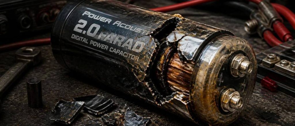
A capacitor with a bulging top, a split or opened pressure vent, or brown/white crystalline deposits around the terminals or can body has physically failed and must be replaced immediately — not tested, not left in circuit, not used further.
The bulging top indicates gas buildup inside the capacitor from electrolyte decomposition or internal short circuit. The pressure vent is designed to open before catastrophic rupture — if the vent has opened, the electrolyte has partially vented (the brown or white deposits are electrolyte residue) and the capacitor’s internal structure is compromised. A capacitor with a vented or open pressure vent is chemically unstable — the remaining electrolyte is contaminated with decomposition products and the capacitor cannot be used safely.
Do not attempt to test a visually damaged capacitor while connected to the electrical system. Disconnect it, inspect it in a well-ventilated area, and dispose of it as electronic waste.
Symptom 7 — Symptoms That Appear and Disappear on Road Bumps or Vibration
System performance that varies with road conditions — amplifier cuts out over bumps, headlights dim intermittently on rough roads but not smooth roads — points to a connection failure rather than internal capacitor degradation. The most likely causes are a loose terminal connection at the capacitor (the ring terminal has backed off the capacitor post), a cracked solder joint inside the capacitor’s terminal assembly, or a loose connection in the wiring between the battery and capacitor.
This intermittent pattern is distinct from the consistent performance degradation of electrolyte dry-out. The system works correctly on smooth roads — proving that when the connection is solid, the capacitor is performing. The fix may be as simple as tightening the terminal bolts on the capacitor posts.
ESR — The Number That Tells You If Your Capacitor Is Actually Working
Every symptom above can be caused by a capacitor with high ESR. High ESR is the hidden failure mode — a capacitor can measure at or near its rated capacitance on a simple DMM capacitance test and still have ESR high enough to make it useless for fast current delivery.
Here’s why that matters for diagnosis. A simple DMM capacitance test charges the capacitor slowly and measures how much charge it stored. ESR doesn’t affect this measurement significantly — the charging rate on a DMM’s capacitance function is slow enough that even a 5-ohm ESR doesn’t meaningfully limit the test current. The capacitor charges fully and reads near its rated capacitance. The DMM reports it as good.
But in the actual audio system, the capacitor faces 50-amp transient demands lasting 50 milliseconds. At 50 amps, a 5-ohm ESR capacitor drops 250V internally — far more than the 12–14V supply voltage. The capacitor cannot deliver the current. The test said “good.” The circuit says “useless.”
The ESR test uses a small AC signal at 100–120 Hz (the standard ESR test frequency) to measure the capacitor’s internal resistance directly. This catches the failure mode that the capacitance test misses.
ESR test values for car audio capacitors:
| ESR Reading | Interpretation | Action |
|---|---|---|
| Below 0.05 ohms | Healthy — low impedance for fast transients | No action needed |
| 0.05 to 0.5 ohms | Marginal — degradation beginning | Monitor; plan replacement |
| 0.5 to 5.0 ohms | Degraded — not buffering effectively | Replace |
| Above 5.0 ohms or open circuit | Failed — acting as resistor in circuit | Replace immediately |
ESR meters capable of testing car audio capacitors are available for $15 to $45 — basic units that test capacitance and ESR simultaneously. Brands like MESR-100, Peak Electronics, and several Chinese imports provide accurate ESR readings for electrolytic capacitors in this size range.
Critical procedural note: ESR must be measured with the capacitor disconnected from all circuitry. The parallel combination of the capacitor’s ESR with the amplifier’s internal capacitors and the battery’s internal resistance produces a falsely low ESR reading in circuit. Disconnect the capacitor from both the amplifier and the battery before measuring.
The Dangerous Failure Modes — What Happens When a Capacitor Shorts or Reverses
Two failure modes go beyond poor audio performance into equipment damage and fire risk.
Polarity Reversal:
An electrolytic capacitor is a polarized component — positive terminal connects to the positive power rail, negative terminal connects to ground. Connecting it backward causes immediate reverse-voltage breakdown of the aluminum oxide dielectric layer inside the capacitor. The dielectric collapses into a conductive path. The capacitor becomes a near-zero-resistance connection between its terminals. Current from the 12V battery flows through the capacitor limited only by wiring resistance — which in a car audio installation with large-gauge wire can reach hundreds to thousands of amps instantaneously.
The capacitor heats within a fraction of a second. Internal gas pressure builds. The pressure vent opens — or if the pressure builds faster than the vent can relieve it, the can ruptures. Electrolyte is ejected. The electrolyte is corrosive and in the case of a violently venting large capacitor, can be projected several feet.
Per NFPA electrical fire hazard guidance, a short circuit in a 12V automotive electrical system with low-impedance wiring can sustain thousands of amps — sufficient to ignite surrounding materials within seconds if the overcurrent protection (fuse) fails to clear quickly. A capacitor installed backward that’s fused correctly blows the fuse and limits the damage. A capacitor installed backward without a fuse or with an overrated fuse can start a fire.
The prevention: Before connecting any car audio capacitor, verify polarity twice — the positive terminal marking (typically a red cable or a + label on the terminal post), the negative terminal marking, and the polarity of the vehicle’s power and ground connections. A polarity check takes 30 seconds. A polarity reversal takes 0.1 seconds and is not recoverable.
Internal Short Circuit:
An internal short occurs when the separator between the positive and negative electrode foils degrades — from age, from physical shock, from contamination, or as a secondary consequence of a polarity reversal that didn’t immediately rupture the can. The capacitor becomes a near-zero-resistance path between its terminals even with correct polarity installed.
The symptom sequence of an internal short: the capacitor charges normally at first (the short is developing, not yet complete), then begins drawing excessive current continuously (the system voltage drops and stays low even without audio playing), then either blows its fuse or, in improperly fused systems, heats the wiring and begins the thermal sequence toward fire.
The fuse check: Every car audio capacitor installation must include an appropriately sized fuse within 18 inches of the positive battery terminal. If the capacitor is wired from a distribution block that already has a fused connection from the battery, that fuse covers the capacitor. If the capacitor has its own run of wire directly to the battery, that run needs its own fuse. Fuse size should be matched to the wire gauge, not to the capacitor’s capacitance — a 1/0 gauge run can carry 200 to 300 amps and needs a fuse rated to protect that wire.
How To Tell If Your Capacitor Has Already Shorted — and Whether It Damaged the Amplifier
If a capacitor failure was sudden — a pop, a burning smell, a blown fuse, or a sudden loss of audio — the post-failure assessment determines whether the capacitor alone failed or whether the fault propagated to the amplifier.
Step 1 — Check the main fuse at the battery:
A blown main fuse at the battery (the fuse on the primary run from battery positive to distribution block) indicates the fault drew more current than the fuse’s rating. This is the expected protection response to an internal capacitor short or polarity reversal. Replace the fuse only after identifying and replacing the failed component — reinstalling a fuse without fixing the fault just blows the next fuse in the same event.
Step 2 — Check the amplifier’s internal fuses:
With the capacitor disconnected from the system, check the amplifier’s internal fuses (typically accessible through a fuse holder or removable cover on the amplifier’s endplate). Blown internal amplifier fuses indicate the fault reached the amplifier’s power terminals before the external fuse cleared — the amplifier’s internal fuses are a secondary protection that cleared to protect the output stage and power supply.
A blown external fuse with intact internal amplifier fuses: the amplifier likely survived. The external protection cleared before the surge reached damaging levels inside the amplifier.
Blown external fuse plus blown internal amplifier fuses: the surge reached the amplifier. The output stage may have been damaged. Test the amplifier independently — connect it directly to the battery (without the capacitor) through a known-good fuse and verify it powers on without protection mode and produces clean audio.
Step 3 — Inspect wiring for heat damage:
A fault that sustained even a fraction of a second before the fuse cleared can heat the wiring near the fault location. Inspect the power wire at the capacitor’s positive terminal for discoloration, melted insulation, or a burned smell. Heat damage to wiring insulation can create a new fault point — damaged insulation that allows the wire to contact metal chassis is a future short circuit. Any heat-damaged wiring section should be cut out and replaced before restoring power.
How To Test a Car Audio Capacitor — Three Methods From Simple to Definitive
Method 1 — Visual Inspection (No Tools, 2 Minutes)
Examine the capacitor’s exterior before any electrical test:
- Top of the can: Should be flat. Any bulging — even slight upward dome of the top surface — indicates internal gas pressure from electrolyte decomposition. A bulging capacitor has failed. Do not test it further while connected to power.
- Pressure vent: The score marks or perforations in the top of the can should be intact and undisturbed. If the vent has opened — visible as a tear or opening in the scored pattern — the capacitor has already vented internally. Failed.
- Terminal area and can body: Look for brown, white, or crystalline deposits near the terminals or on the can body — electrolyte residue indicating leakage or venting. Look for corrosion on the terminal posts or ring terminals.
- Can body: Should be straight and undamaged. Any cracks, dents near the terminals, or signs of previous overheating (discoloration) indicate physical damage.
A capacitor that passes visual inspection proceeds to electrical testing. A capacitor with any physical damage fails here and goes to recycling.
Method 2 — Voltage Comparison Test (DMM Only, 5 Minutes)
This test evaluates whether the capacitor is buffering voltage during bass transients — its actual job performance.
- Set your DMM to DC voltage and connect the probes to the capacitor’s positive and negative terminals — not to the battery or distribution block, specifically to the capacitor’s terminal posts.
- Play a bass-heavy track at approximately 75 percent volume through the subwoofer system.
- Watch the voltage reading during bass hits.
Healthy capacitor result: Voltage at the capacitor terminals stays within 0.3 to 0.5V of the system’s resting voltage during bass transients. If resting voltage is 13.8V, it stays above 13.3V during hits.
Degraded or failed capacitor result: Voltage at the capacitor terminals drops the same amount as the system voltage during bass transients — 1V, 2V, or more. The capacitor is not buffering. It’s following the system voltage down rather than holding it up.
This test doesn’t quantify how badly the capacitor has failed, but it definitively confirms whether it’s doing its job.
Method 3 — ESR and Capacitance Measurement (ESR Meter, Definitive)
Disconnect the capacitor from the circuit — both the power connection and the ground connection. Allow 5 to 10 minutes for the capacitor to fully self-discharge before touching the terminals. A large capacitor charged to 13V stores enough energy to produce a painful or dangerous shock.
Connect the ESR meter leads to the capacitor’s terminals according to the meter’s polarity markings. Take the ESR reading first, then the capacitance reading.
Compare against the pass/fail values:
| Measurement | Healthy | Marginal | Failed |
|---|---|---|---|
| ESR | Below 0.05 Ω | 0.05–0.5 Ω | Above 0.5 Ω |
| Capacitance | Within 20% of rated value | 20–50% below rated | Below 50% of rated |
A capacitor that passes both tests is electrically healthy — investigate the wiring or the capacitor’s size match to the amplifier’s demands rather than the capacitor’s internal condition.
A capacitor that fails either test warrants replacement — particularly ESR failure, which directly limits the capacitor’s ability to deliver fast current transients regardless of remaining capacitance.
Does Your System Actually Need a Capacitor — or Is Wiring the Real Problem?
Here’s the question the car audio community debates endlessly and that most capacitor articles never address: a stiffening capacitor treats a symptom. The wiring is often the disease.
Before replacing a failed capacitor with a new one, understand what the capacitor is and isn’t capable of solving in your specific system.
What a capacitor can fix:
A stiffening capacitor is effective at buffering instantaneous, brief current demands — individual bass transients lasting 50 to 200 milliseconds where the amplifier needs a large current spike that the battery and alternator can’t deliver quickly enough. In a system with otherwise adequate wiring, a capacitor eliminates voltage sag on those individual transients. Headlights stop dimming on individual kicks. The amplifier maintains its rail voltage through each hit.
What a capacitor cannot fix:
A capacitor cannot compensate for sustained current deficit. Its storage capacity — even a 4-farad unit at 13.8V — represents approximately 30 joules of energy. At 50 amps of sustained demand, that energy is depleted in approximately 0.6 seconds. For a bass-heavy track at high volume with sustained amplifier demand, a capacitor runs out of stored energy within the first second and provides no further benefit — the system is now running entirely on whatever the battery and alternator can deliver through the wiring.
If the power wiring from the battery to the amplifier is 4-gauge when the amplifier demands 1/0 gauge for its power rating, the wiring’s resistance limits sustained current delivery. A capacitor doesn’t change the wiring resistance. It helps on individual bass hits. It cannot help during sustained high-volume listening.
The diagnostic test that tells you which problem you have:
Play a loud, bass-heavy track at high volume. Note when the problems occur:
- Problems on individual loud bass hits but not during sustained passages: The amplifier is drawing more instantaneous current than the battery can deliver quickly. A capacitor is the appropriate solution.
- Problems throughout a high-volume bass-heavy track, not just on individual hits: The sustained current demand exceeds what the wiring can deliver. The wiring is the root cause. A new capacitor will fail to solve this.
- Problems consistently at a specific volume level regardless of bass content: Gain is set too high, causing the amplifier to clip. This is not an electrical supply problem — it’s a signal chain calibration issue. Neither a capacitor nor wiring upgrades fix gain-induced clipping.
The Big 3 wiring upgrade:
The “Big 3” refers to replacing three specific wires in the vehicle’s electrical system with heavier gauge wire:
- The ground wire from the battery negative terminal to the chassis
- The ground wire from the engine block to the chassis
- The wire from the alternator output to the battery positive terminal
These three connections are the highest-current paths in the vehicle’s electrical system. Replacing them with 1/0 or 2/0 gauge wire (from the factory 4 to 6 gauge on many vehicles) reduces the resistance in the charging and distribution circuit, allowing the alternator to deliver its full rated output with minimal voltage drop. The Big 3 upgrade costs $30 to $80 in materials and takes 1 to 2 hours — significantly less than a quality capacitor and addressing a different (often more fundamental) electrical limitation.
A system with the Big 3 complete and adequate amplifier power wiring may not benefit significantly from a capacitor. A system with the Big 3 complete and adequate wiring that still shows headlight dimming on individual bass hits would benefit from a capacitor. Both can coexist — the wiring fixes the sustained supply, the capacitor handles the transient spikes.
Capacitor Replacement and Installation — What To Do Differently This Time
If the diagnostic confirms the capacitor is the problem and the system design is appropriate for a capacitor (short transients, adequate wiring for sustained current), replace it correctly to avoid repeating the failure.
The charge resistor procedure — the step most people skip:
A stiffening capacitor starts at 0V when new. Connecting it directly to a 12V battery creates an instantaneous near-short-circuit condition — the capacitor’s impedance at 0V is near zero, so the inrush current is limited only by wiring resistance. On a 1/0 gauge wire with very low resistance, this inrush can exceed 1,000 amps for a fraction of a second. This instantaneous current spike damages the capacitor’s internal connections, can weld relay contacts in the vehicle’s electrical system, and can damage the amplifier’s power supply if connected before the capacitor is pre-charged.
The charge resistor pre-charges the capacitor slowly before making the main battery connection:
- Connect the negative terminal of the capacitor to ground (chassis) first.
- Connect the positive terminal of the capacitor to the battery positive through a 1k-ohm, 10-watt resistor — most capacitor kits include this resistor; if not, a standard wirewound resistor from any electronics supplier works.
- Wait 30 to 60 seconds — the capacitor charges through the resistor at a controlled rate. The integrated voltmeter display (if present) will rise from 0V to approximately battery voltage as it charges.
- Once fully charged, remove the resistor and make the direct connection. The inrush current at this point is essentially zero because the capacitor is already at battery voltage.
Polarity verification before any connection:
Label the positive and negative terminals of the capacitor before installation. Check the polarity of the vehicle’s power and ground connections with a DMM before connecting anything. Verify positive to positive, negative to negative. There is no recovery from a polarity reversal on a large capacitor — it’s immediate physical failure.
Mounting location:
Mount the capacitor in a location that minimizes heat exposure. The trunk area of most vehicles reaches 130°F to 160°F on hot days — acceptable for a capacitor rated at 85°C (185°F). Under-seat locations in direct sunlight can exceed these temperatures. Avoid mounting directly on the amplifier chassis (which generates its own heat) and keep the capacitor away from exhaust heat paths. The cooler the operating environment, the longer the electrolyte lasts.
Wire length from capacitor to amplifier:
The capacitor’s benefit diminishes with the length of the wire between it and the amplifier’s power terminals. The inductance of the power wire adds impedance that slows the capacitor’s current delivery — reducing its effectiveness on fast transients. Mount the capacitor as physically close to the amplifier as the installation allows — ideally within 12 inches of the amplifier’s power terminal.
Capacitor Replacement Cost and When to Skip It Entirely
The financial decision for a bad capacitor depends on what the capacitor was actually doing in the system and whether it was solving the right problem.
| Scenario | Recommended Action | Cost |
|---|---|---|
| Capacitor failed (high ESR, low capacitance), wiring adequate | Replace capacitor | $30–$150 parts; DIY installation |
| Capacitor failed, wiring undersized for amplifier | Upgrade wiring first, then evaluate whether capacitor is still needed | $30–$80 Big 3 materials; $100–$200 shop installation |
| Capacitor physically damaged (bulge, vent, leak) | Replace immediately; inspect wiring for heat damage | $30–$150 replacement + $0–$200 wiring repair if needed |
| Capacitor tests healthy but symptoms persist | Investigate wiring, alternator output, and amplifier gain | $0 for self-diagnosis; $75–$150 shop diagnostic |
| System doesn’t have Big 3 upgrade, capacitor is failing | Consider Big 3 upgrade before or instead of capacitor replacement | $30–$80 DIY Big 3 materials |
When a capacitor isn’t worth replacing:
A capacitor in a system with severely undersized power wiring won’t solve the persistent symptoms regardless of its condition. If the symptoms are present throughout sustained high-volume listening (not just on individual transients), replacing the capacitor with a new unit of the same capacitance will produce the same symptoms — because the wiring limitation, not the capacitor, is the root cause. In this scenario, the better investment is the Big 3 wiring upgrade first, then re-evaluation of whether a capacitor adds meaningful further improvement.
A capacitor also isn’t worth replacing if the amplifier system is undersized for the connected subwoofer — a 200-watt amplifier driving a 1,000-watt subwoofer at sustained high volume isn’t a power supply problem, it’s a system design mismatch. No capacitor fixes that.
FAQs About Bad Car Audio Capacitor Symptoms
Can a bad capacitor damage my amplifier?
A capacitor that fails through an internal short can send a high-current surge through the amplifier’s power terminals in the moment before the external fuse clears. Whether this damages the amplifier depends on how quickly the fuse clears and what the amplifier’s internal fuses see. Check the amplifier’s internal fuses after any capacitor failure event — blown internal amp fuses indicate the surge reached the amplifier and the output stage should be tested before reinstalling. An amplifier that works normally after a capacitor failure event (powered on without protection mode, produces clean audio) is likely undamaged.
How long do car audio capacitors last?
In a typical car trunk environment (moderately hot, moderate vibration), a quality electrolytic stiffening capacitor lasts 3 to 7 years before ESR increases to a level that affects performance. Capacitors in very hot environments (under direct sun exposure, near heat sources) fail faster — sometimes within 18 to 24 months. Capacitors in cool, ventilated locations can last 10 years or more. The primary life-limiting factor is temperature — every 10°C reduction in operating temperature approximately doubles the capacitor’s expected service life, per standard electrolytic capacitor aging models.
Is my capacitor bad if the digital display shows the wrong voltage?
Not necessarily. The integrated digital voltmeter display is a separate circuit from the capacitor itself — a failed display doesn’t mean the capacitor has failed electrically. Measure voltage at the capacitor terminals with an external DMM and compare to system voltage. If the external DMM reading matches what a healthy system should show (within 0.5V of battery voltage at rest, minimal sag during bass hits) and the ESR tests healthy, the display circuit has failed but the capacitor is functional. Display-only failure is a nuisance, not a performance problem.
Do I need to use the charge resistor every time I disconnect and reconnect the capacitor?
Yes, if the capacitor has discharged to 0V during the disconnection period. If you’re disconnecting the capacitor briefly to move it and it retains charge near battery voltage, reconnecting it without the charge resistor is safe — there’s minimal voltage differential and minimal inrush. If the capacitor has been disconnected and discharged fully (which it will do within minutes to hours through its own leakage current), use the charge resistor procedure before reconnection.
Can a bad capacitor cause alternator whine in the audio system?
A degraded capacitor with high ESR can actually make alternator whine worse rather than better. A healthy capacitor filters some of the alternator’s ripple voltage from the power supply, reducing the AC noise component that appears as alternator whine in the audio signal. A capacitor with high ESR provides less filtering — the ripple passes through rather than being absorbed. However, a capacitor alone rarely fully eliminates alternator whine — a noise filter or ground loop isolator on the signal path is more effective for that specific problem.
The Expert Verdict
A bad car audio capacitor is easy to mistake for several other problems — alternator issues, amplifier protection trips, gain miscalibration — because the symptoms of a dead capacitor are identical to a missing one. The diagnostic sequence cuts through the confusion: visual inspection first (any physical damage = failed), voltage comparison test second (buffering within 0.3–0.5V = working), ESR measurement third (below 0.05 ohms = healthy, above 0.5 ohms = replace).
The more important question than “is my capacitor bad” is “is a capacitor the right solution for my specific symptoms.” A capacitor fixes transient voltage sag on individual bass hits. It doesn’t fix sustained current deficit from undersized wiring, and it doesn’t fix gain-induced clipping. Get the diagnosis right before buying anything — because a new capacitor in the wrong system produces the same symptoms as the old one.